Part
In this dialog you can change the shortening options of the side-views as well as configure the extra section views and end plate views.
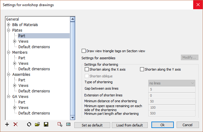
In this dialog box you can change the following options :
Draw view triangle tags on section view - When enabled, this will draw triangular annotations with the view numbers next to each side view and also on the section view: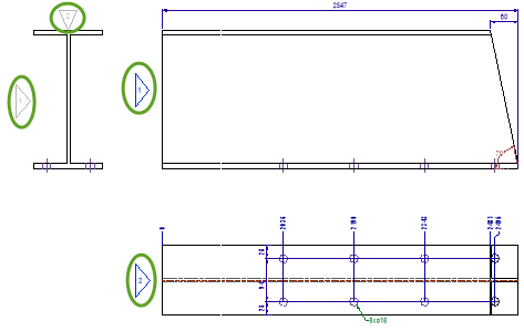
Settings for assemblies - For more about these options, see the Assembly-specific settings topic.
Shorten along the X or Y axis - When active, the side views will be shortened linearly to save space on the sheet. The side views are always shortened equally.
Features such as holes or cuts are not shortened.
Use the options below to configure the 'aggressiveness' of the shortening.
Shorten oblique - When active, also oblique lines will be shortened.
Type of shortening - Choose the type of lines that should be drawn at each break location that was created by the shortening.
Gap between axis lines - This is the small gap between two shortening lines. If no shortening lines were chosen this will create a small opening of the shortened lines.
Extension of shorten lines - How far the shortening lines should extend beyond the model lines of the part.
Minimum distance of one shortening - The minimum distance that is required between 2 features. If the distance is smaller, the shortening will not be done. This value will prevent shortenings being created between the holes of a hole pattern.
Minimum open space remaining on each side of the shortening - The open space that needs to be kept between the shortening line and the feature.
Minimum part length after shortening - The minimum length of the part after all the shortening have been applied. This setting will avoid a 8000mm long profile being shortened into a 50mm part, which would look strange on the sheet.