A “sphere” represents a connection. For this sphere you must imagine yourself a collection of data that holds the intelligence of the elements of the connection.
When a base profile of a connection is modified, then the sphere will ensure that the elements in that connection adapt automatically to that modification.
We call this sphere a macro because this sphere can contain not only connections but also larger elements such as a tread, a cage ladder, the wire frame of a building,….
To modify the dimensions of a connection you use the command Review macro  .
.
Afterwards you select the macro (sphere) that you wish to modify.
(it is also possible to adapt several macros at the same time, see further in the manual)
The dialog box that follows has a functionality that most dialog boxes do not have:
The dialog box is not fixed to a command. This means that while this dialog box is active, you can start any other command. The dialog box is always open until you close it. You can even open several of these dialog boxes at the same time that for example each adapt other macros.
It is possible in this dialog box to modify the dimensions of several macros at the same time.
At the bottom of this dialog box there are some options that are to be used to select which macro(`s) must be edited.
You can do this by selecting several macros while starting this dialog box or afterwards by pressing the button  Select other macros.
During the selection process you can select other elements except macros (for example the complete project). The elements that are not relevant will be ignored.
To prevent the editing of several macros becoming chaotic each macro belongs to a group.
You can only edit one group of macros at the same time.
Select in the first list the group that you wish to edit.
In the second list you can choose to edit all macros in the group, or only one of the macros. This second list is therefore dependent on the group that you have selected: the list will be updated each time you select another group.
When you edit several macros at the same time, the tabs and dimensions of all these macros are added in this dialog box.
The dimensions with the same name are reflected as one dimension and get behind the name between brackets a number that indicate at how many macros the dimension represents. The value of the dimension becomes *VARIES* if the values from the different macros differ. You can simply modify this value: the dimension will be applied to all macros that have the dimension.


 Use these icons to change the view to one of the side views of the connection.
 Whenever you modify a dimension of the connection, then the complete connection will be checked for collisions. This icon works as a switch to enable or disable this automatic clash control. It can be useful to turn it off when you edit a large connection or many connections simultaneously and the clash control demands too much calculation time.
 With this button you can choose from the library another connection for the current connection (s). This works more rapidly than to remove the macro and to apply a new one. The dimension values of the current connection will be copied to the new connection where possible.

 With these icons you can save all values of the current selected connection (s) under a name and recall them at a later time. A value list can only be loaded if the connection is compatible with the connection with which the value list was made (this means the name of the macros must be identical).
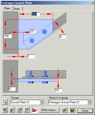
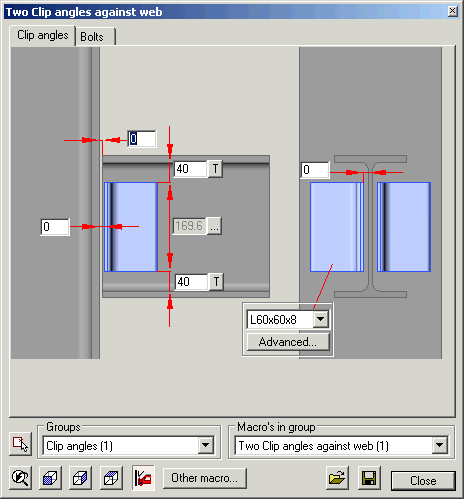
On top of this dialog box there are a number of tab pages.
Each tab contains dimensions and/or options of a certain component of the macro.
The number of tabs and the contents of it are therefore dependant on the macro. There are 3 types of tabs:
Ordinary tab
This tab only contains dimensions.
Bolts tab
This tab contains dimensions such as the ordinary tab but also contains special options for bolts.
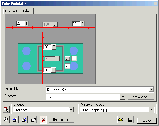
In the above example we have one bolt pattern. Each bolts pattern has two adjustable values that indicate the number of bolts vertically and horizontally.
Keep into account that not all bolt patterns have two numbers. There are also line and circle patterns that have but one number.
Besides the fields of the number of bolts there is always a button ‘…’.
If you click on this button then you can change advanced settings of the pattern:
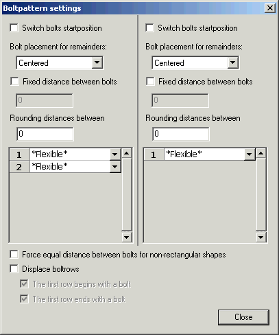
Some of these options need some more explanation.
Columns horizontally/vertically: All options are double to enable us to modify all the options separately horizontally and vertically (if the pattern is rectangular).
Fixed distance between bolts: The distance that you enter will always be respected. The option Bolt placement for remainders is important in combination with this option because with it you stipulate at which side the remaining distance will be placed.
Rounding distances between: This is an important option to avoid undesirable distances. Imagine that we have a pattern with a length of 100 mm. You choose 3 bolts for this pattern. The bolts are divided equal and as a result we get a distance between the bolts of 33.33 mm. Later that distance (rounded to 33 or 33.5) will be put on the workshop drawings, which is of course undesirable!
We avoid this by setting the rounding to 1 (or 5 or 10?). The distance between bolts is taken never smaller than the number that you enter here. Therefore with this option the bolts will never be drawn at distances of 33.33 but at distances of 33, or 35 or 30, depending on the rounding you choose.
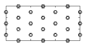
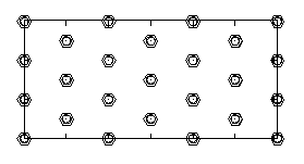
Force equal distances between bolts for non-rectangular shapes:
In the next image the option is off and in the second image it is on:
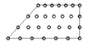

If you enable this option, the bolts that fall outside of the pattern will be removed.
Displace bolt rows:
With this option enabled the bolt rows will alternate with an open spot:
The first row begins with a bolt:
With this option enabled the arrangement of the bolts changes:
At the lower part of the tab there are some general options that have influence on all of the bolts of all patterns in this tab.
The options explain themselves except in the dialog box that you get if you click on Advanced.
Slot holes.
You can activate the slot holes for each drilled element. Each drilled element receives a number. The first drilled element is the element that lies the closest against the head of the bolt. The numbers of the following elements continue to go upwards from there.
Profiles tab
This tab contains several properties that have influence on the profiles in the tab.
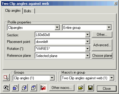
In the lower part of the tab the placement and the section of the profiles can be modified.
Because this tab can contain several profiles we work with groups of profiles.
With the upper 2 selections you choose which profiles you want to modify.
The first selection is the group.
With the second selection you choose which elements from the group you wish to edit.
In the above example the complete group was chosen. Each profile has its own, unique number like for example 1074631000.
You have the possibility to edit each profile separately by selecting the number in the list.
The options that we see on the tab itself are a limited selection. You obtain a collection of all possible options with the button Advanced.
That dialog box is explained in the Place profile chapter.
Below we have a button Segmented profiles.
Some profiles can be segmented.
The intention is to treat the profile as one profile on a polyline, but to split this profile on chosen distances.
In the dialog box you choose on top one of the segmented profiles.
At this moment you can modify the options of that profile:
New name: Modify the unique name of this profile (name for in selection list).
Offset: The offset that must be used for each break.
List with segmentation points: The list gives the absolute distance of each segmentation point on the profile. You can remove some or add new with the buttons underneath.
The distance starts from the first point of the line (this is the first point which you indicate during drawing the polyline).
The button Indicate new point on screen is a tool to add new segmentation points. You can add a segmentation point by selecting a point on the line of the profile. The correct absolute distance of the point that you have selected will be calculated and added to the list.