The annotations are meant to show extra information about a part on the 2D sheet, or for showing the level at a certain point.
You can also draw annotations in model space between the 3D parts, but drawing them this way is less advantageous.
The different types of annotations can be drawn with the following commands :

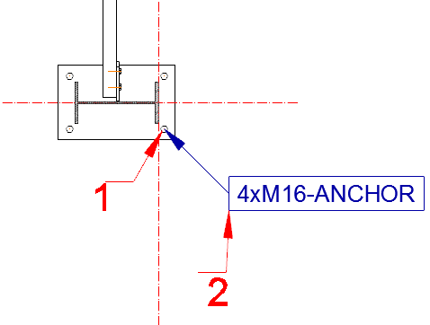
For the first point you indicate the part that needs to be annotated.
For the second point you give the location of the frame.
We will go more into detail for each command :
 Will display the position number + name of the member or plate, the name+standard for bolts and the diameter for a hole.
 Will display the assembly number+name for a member or plate, the name+standard for a bolt and the diameter for a hole.
 Will only display the name of a member or platen, the name of a bolt and the diameter for a hole. This is useful for the plans that need to be submitted for approval.
 Allows you to add a comment to any object.
 Allows you to measure the height of the object in 3D.
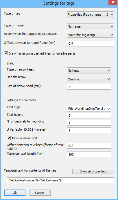
The appearance of the annotation can be adjusted in the AutoCAD Properties dialog box.
You can modify the standard settings by starting one of the above commands and you immediately press S and <Enter>.
In the list of the dialog box Managing annotation styles you can change the style of each type of annotation.
There is a separate style for each type of annotated object so that we can choose a different frame, text style and text height for each type of object.
We will go into more detail on some of the settings of the annotation style :
It is also possible to create your own icon that will draw new annotations. To do this, proceed as follows :
and then pressing S and <Enter>.