Profiles are based on model lines.
You can place profiles on the following line types:
• Line
• Arc
• 2D Polyline
• 3D Polyline
• Spline
Each of these 8 icons will start the profile-selection dialog box with the corresponding tab as standard selection.
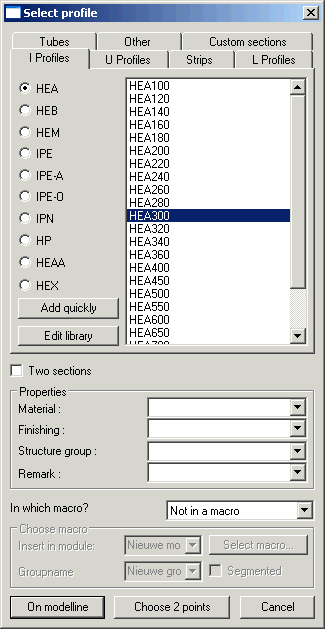
Make your profile choice from the lists.
It is possible to edit the library from here by clicking on the button edit library. See chapter Editing the profile library for further information.
Below the profile selection you can enter 4 properties that the new profiles will receive. For each of these 4 properties you have the possibility to make a list with standards, so that you do not have to retype the property each time. You can produce the lists in the dialog box: Parabuild Settings > tab Global > button Advanced.
The bottom settings are only relevant if you wish to add the new profiles to a macro. This is useful if you wish that the profile makes itself dependant on the model line with which it was drawn. If the model line changes, the profile will modify automatically. It is the macro that keeps the link between the line and the profile intact.
This link works only in one direction: the profile is dependent of the line and not reversed.
By way of illustration:
Profile is moved. Consequence: Profile automatically moves back to the original placement on the line.
Line is moved: Consequence: Profile moves with the line.
If you add a profile to a macro, you also have the advantage that you can for example later modify the rotation of the profile with one click on the button by editing the relevant macro.
The link between the profile and the line is removed if the line, the profile or the macro is removed.
You have the choice to make a new macro or to insert the profiles in an existing macro.
If you choose to add the profiles to a macro, then you must still choose in which module the profile must be saved and also a group name for the profiles. You can choose an existing profile module from the list. If you type a profile module that does not exist, a new one will be created.
The group name allows you to add several profiles under one name, with the goal to be able to modify the placement of these profiles simultaneously.
For example all columns at the left-hand side of the building have the same rotation and the same reference plane, so it is useful to give them one group name e.g. columns-left.
Entirely below there is one remaining option: “segmented”. If you activate this option, you will be able to use the macro to break the profile in segments on distances you choose. This option was made for drawing handrails.
For this you must have drawn one long polyline as a base line for the handrail.
After you have modified all options to your wish you must click “on model line” or “indicate 2 points”.
With the first button you must select one or more lines.
The last button will draw a new line after you have indicated 2 points.
Finally we see the Profile Placement dialog box.
With this dialog box we stipulate the correct position of the profile on the model line on which it is based.
The new profiles were already drawn at this moment. When you modify an option you can directly see the result on the screen.
Profile placement
Beside the 9 placements on the image there still are 3 other possibilities available in the list:
Manually: You can indicate a point yourself on the section or type in 2 coordinates.
Start point of polyline: We mean the beginning point of the polyline of the section.
Neutral axis: The balance point of the section.
Rotation:
The rotation of the section around the model line.
Reference plane:
• WCS: Bases the placement according the World coordinates of the drawing.
• Current UCS: Bases the placement according the current UCS coordinates.
• Coordinate system: If you have created coordinate systems in the drawing, and you give these a name, then you are able to choose in the list one of the coordinate systems as a basis.
• Other: You must manually select the reference plane on which the rotation of the section will be based. You can indicate as a reference plane the surface of a polyline or one of the planes of a profile that already exists.
Create profile on one segment of the polyline:
When you have chosen as model line a polyline that contains several lines (=segments), then you can choose here to place the profile on all lines or on one of the lines. For the last option you must fill in the number of the segment (the first segment has number 0).