The arrangements of the views on the shop drawings are much more adjustable now.
The easiest way to configure the views is with the Pre-configure view arrangement dialog box.
This dialog box is available from the workshop settings.
It is only available for profile and assembly drawings : 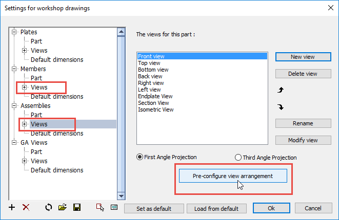
The Pre-configure dialog box will change and re-arrange the views of the profile or assembly settings.
We will discuss the options in this dialog box :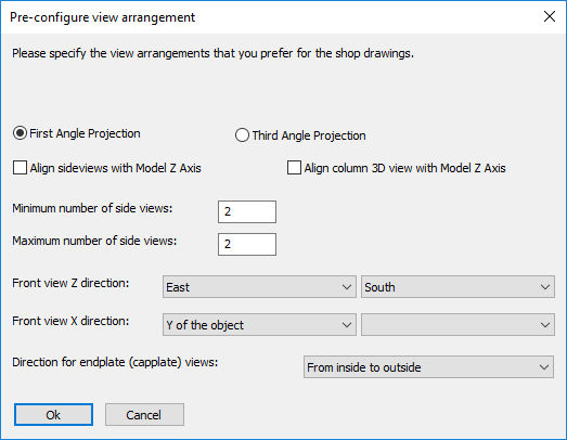
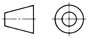
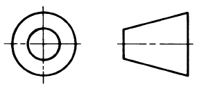
The view arrangement of all side views and section views will be re-arranged to satisfy the First-Angle or Third-Angle Projection rules.
Align side views with model Z
When activated, columns will be drawn upright, beams horizontal, rafters sloped, etc...
Each part will have the same slope in 2D as it does in 3D.
When deactivated, the main member of the assembly will be drawn horizontal on the page.
Align column 3D view with Model Z axis
When activated, the 3D view of columns will be drawn upright.
The 3D view of all other assemblies will be drawn horizontal, even rafters and bracings.
Minimum/Maximum number of side views
The difference between the minimum and maximum number of sideviews determines how many sideviews will be activated dynamically.
A dynamically chosen sideview is a view that will only be drawn when there are parts on the view that need to be dimensioned.
If you want a fixed number of views, set minimum and maximum to the same number.
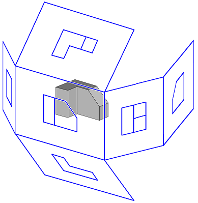
Front view Z direction
The Front view is the main view, on which most other views are based.
The Z direction is the viewing direction.
When one of the cardinal directions is chosen, the AutoCAD/BricsCAD variable NORTHDIRECTION will be used to determine the cardinal directions in 3D. The front view will then point to the North/South/East/West direction in the 3D model.
Direction of Endplate views
For example, From outside to inside : 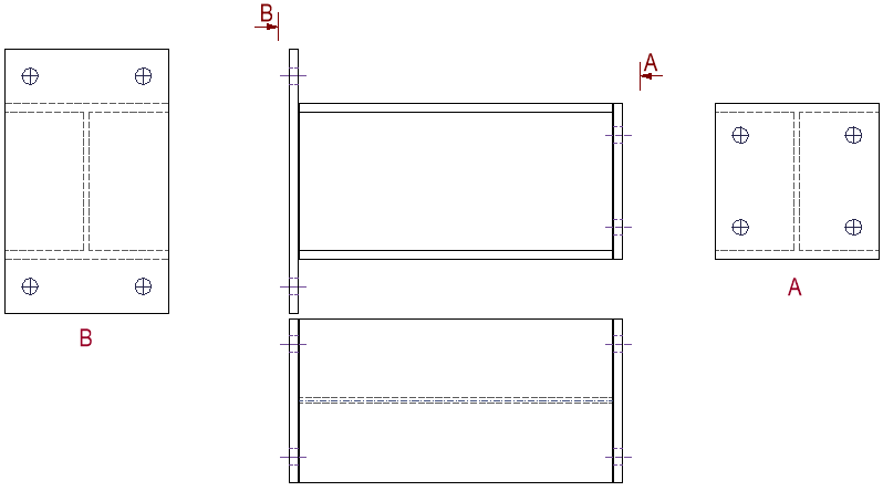
And From start to end : 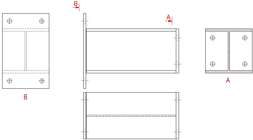
More advanced options are available per view
These are accessible through the Configure view directions and placement button : 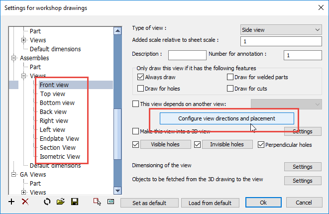
Note that the Pre-Configure dialog box can undo the changes that you apply in this dialog box.
It is therefore best to first use the Pre-configure dialog to configure the views.
If needed you can tweak the arrangement some more with the Configure view directions and placement dialog box per view.
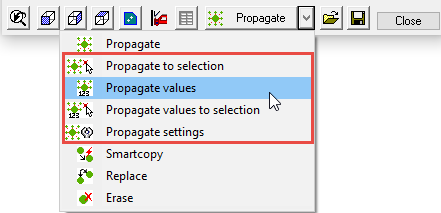
Propagate now has several new commands :
Propagate to selection
Works the same as the normal propagate, but it will only propagate to a selection of profiles, instead of the entire drawing.
Propagate values
This command will not propagate any geometry. Instead it will only propagate the sizes of the macro that is currently being edited.
The sizes will be copied to the macros of the same type. , and with roughly the same geometrics.
Propagate values to selection
Works the same as the propagate values, but it will only propagate to a selection of profiles, instead of the entire drawing.
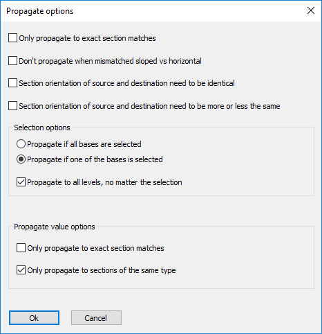
Propagate settings
With these options, it is possible to influence the behaviour of the propagate commands.
![]() Watch the stairs & railings tutorial here
Watch the stairs & railings tutorial here
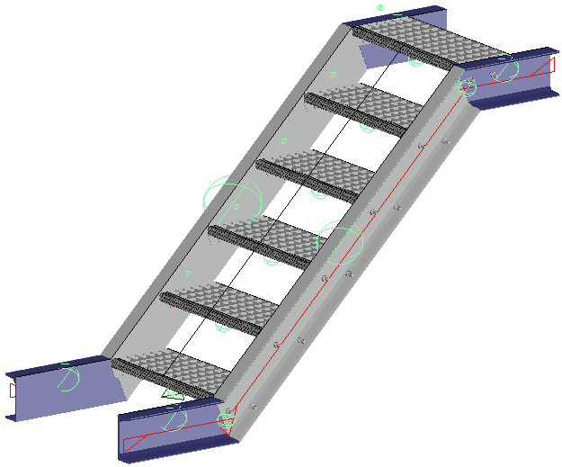
There are 3 methods of drawing a stair in Parabuild.
Each stair method requires different geometry selection.
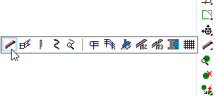
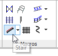
But all 3 methods are accessible from the same command.
We will explain all 3 stair methods.
To draw this type of stair, you need a beam (A) and a horizontal geometry (B) for the location of the stair..
After starting the command, select the beam (A) to which the stair needs to connect.
The side of the beam that you select will determine on which side the stair will be drawn.
After the beam selection, press <Enter> to draw a stair that starts at the ground floor.
The last selection prompt is a "Horizontal geometry" (B). It determines the horizontal offset of the stair on the beam.
This can be a manually drawn line, a gridline or a surface plane on a profile. But it is important that the line or plane is not parallel to the beam.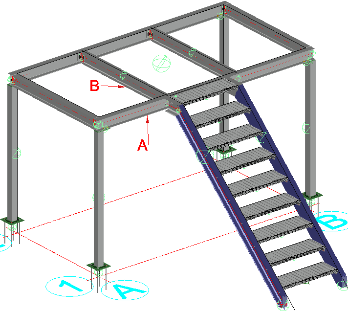
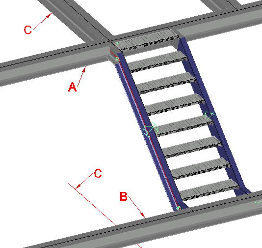
To draw this type of stair, you need 2 beams (A and B) and a horizontal geometry (C) for the location of the stair..
After starting the command, select a beam (A) and then the other beam (B).
The last selection prompt is a "Horizontal geometry" (C). It determines the horizontal offset of the stair on the beams.
This can be a manually drawn line, a gridline or a surface plane on a profile. But it is important that the line or plane is not parallel to the beams.
To draw this type of stair, you will first need to draw a line which will determine the start, end, length and slope of the stair.
After starting the stair command, just select the line and your preferred stair will be drawn on top of it.
![]() Watch the stairs & railings tutorial here
Watch the stairs & railings tutorial here
Railings can be drawn on top of a separate line, or on top of the edge of a profile.
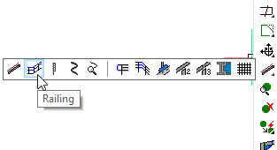
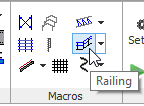
When you start the command, just select the line or edge on which you want to draw the railing.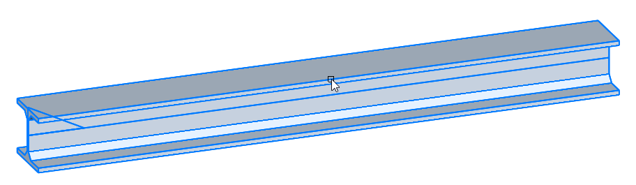
The new railing will be drawn on top of the edge that you select. So the side of the beam that you select is important.
After the edge selection, you will get another prompt for an optional geometry.
You can use this selection when the edge that you selected is actually too long, and you don't want to draw a railing that long.
Select an edge or a surface plane of another entity that is not parallel to the edge that you first selected : 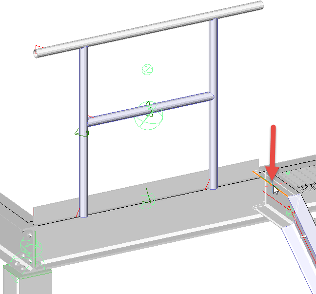
With that selection, there are 2 possible sides on which Parabuild could draw the railing on.
Parabuild takes the side closest to the location where you selected the edge.
When the first segment is drawn, the command does not end but the previous questions are repeated : the prompt for the next edge or line for a new railing segment is asked again.
Parabuild attempts to connect the current railing to the previous railing.
It is therefore best to draw the railings in subsequent order so that the connections between the railings are drawn automatically :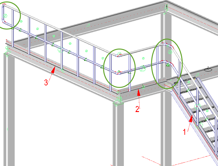
The railings that are not connected will get an ending connection at the end of the command.
Ending connections and intersecting connections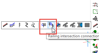
The railing command draws these types of connections automatically.
It will attempt to connect the current railing with the previously drawn railing.
And at the end of a railing it will draw an ending connection.
But these connections will not always be drawn exactly according to your requirements.
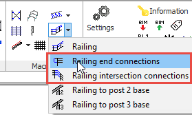
You can simply erase the unwanted macros ( ), and use one of these commands to connect railing.
These commands are unique, because you just need to select the handrails and the last posts.
It does not matter if you select more posts or kneerails. The sequence is also not important.
Parabuild will try to automatically connect all the members in the selection using the connections in the chosen library group.
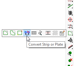
It is now possible to automatically convert a strip to a plate, or a plate to a strip.
Floors are accessed by the Select profile dialog, of which there are 4 options:
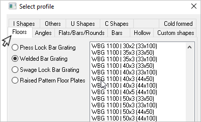
The libraries list the panels in standard widths: 800 - 900 - 1000 - 1100 - 1200.
For panels outside of these standard widths, it's possible to edit the libraries - which will be discussed later.
Grating is drawn as a normal strip, therefore it can be stretched or shortened like any other profile. They may also be modified to include cut-outs using the Modify Profiles / Plates command.
Note that the Bearer-bars (span) will always run in the direction of length.
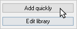
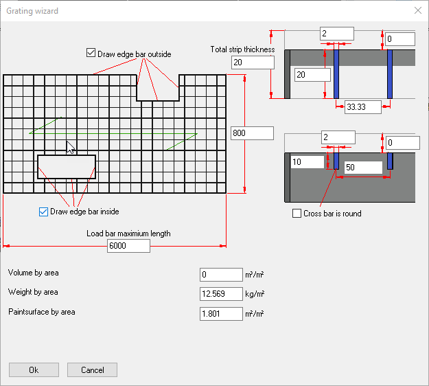
Selecting Add quickly will bring up the following dialog. From here, it's possible to modify a number of parameters including:
Note! these parameters should be revised to suit the particular manufacturer's specifications
Your revised parameters will be automatically stored in the relevant library table.
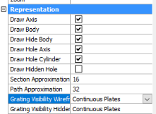
For grating, you can change the visibility of the grating bars at any time in the view manager or in the properties :
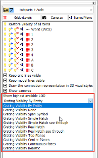

These can improve visibility or performance in very large projects.
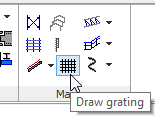
This command is for drawing floor grating over a wider surface area.
The user is prompted to select the entities representing the boundary members of the floor area.
The grating will be drawn to the extremities of the selected entities - they will conform to the selected 'standard' width with the last panel being adjusted to suit the overall dimension.
The following dialog will appear providing the user with the opportunity to revise the following parameters: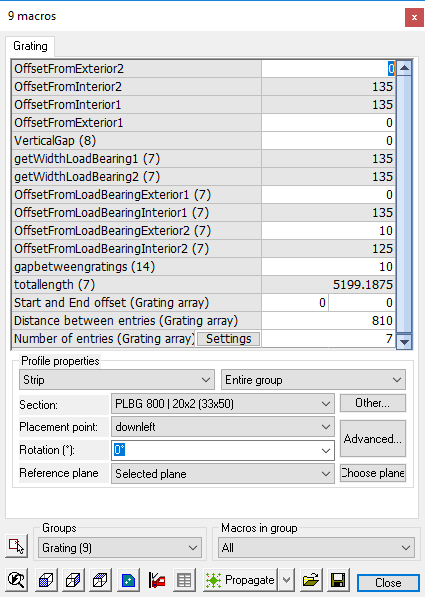
Offsets: which measure the distance between the extremity of the profile and the banded edge of the grating panels.
Section: Indicates the parameters of the grating panel -the user may select from the drop-down menu any other grating panel size from the library
Other: allows the user to select grating from a different group.
Placement point: represents the placement indicator for placing the grating panels - the Advanced button will provide a visual indicator.
These modifications will apply to the grating pattern as a whole. But panels may also be modified independently.
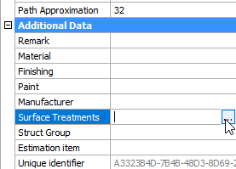
You can now apply surface treatment to any surface of a profile or plate.
This treatment will influence the numbering, so if the treatment of all the surfaces are not the same then the parts will get a different pos/mark number.
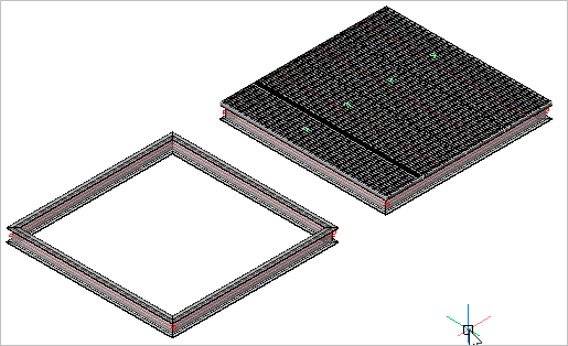
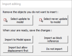
A new 'review' step has been added, which allows you to do the following things just before the file is imported :
Parabuild now also stores and reads unique numbers of the parts.
This allows you to import multiple versions of the project.
When importing a new version of the same project, Parabuild will not just draw new parts,
Instead it will update the parts that already exist in the model.
This tool will generate a step file for each position number in the drawing.
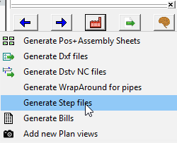
STEP file is a CAD file format, usually used to share 3D models between users with different CAD systems.
The number of parts to be produced is added to the name of the file : "PR5 x 6.stp".
The step file is needed for CNC machines that can automatically cope (plasma/laser) hollow profiles.
This command will only work in BricsCAD and when the Communicator module is installed and licensed.
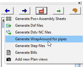
It is now possible to automatically generate the wraparound for all pipes in the drawing.
You can now create one or more drawings that contain "off the shelf" parts.
The parts should have a unique position and/or mark number.
For example, a plate in this drawing should not get the posnumber "PL1".
Instead, it should have a posnumber "STD1" or some other prefix that is not used in normal drawings.
Parabuild will use the "STD1" number for the part whenever it encounters the same part in a drawing.
This way it is clear that the part can be taken from the stock instead of having to be produced again.
Parabuild will also copy the properties from this part.
This way, you can assign specific numbers and properties to off the shelf parts.
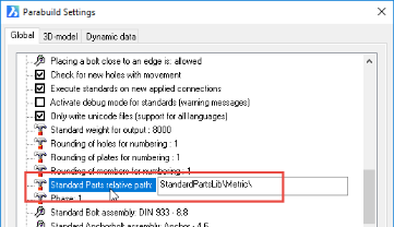
The folder where Parabuild searches for such drawings is :
A ProNest PNL Job file is always generated automatically whenever dxf files are generated.
The file is located in the same location as the dwg file.
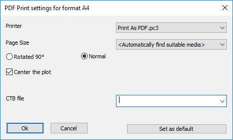
Store PDF print settings
You can now configure and store the PDF printer options.
Before, this was only possible with regular printing.
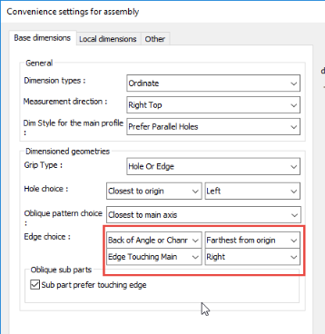
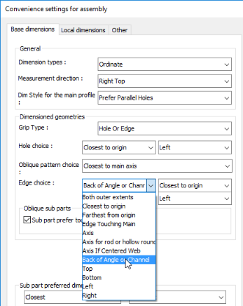
The edge choice option for dimensioned parts now has 4 possible options.
There is also a new entry available, named Back of Angle or Channel.
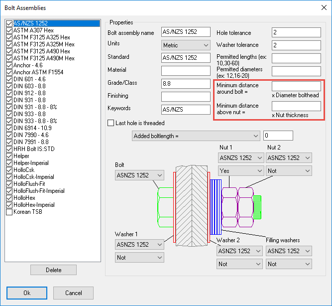
It is now possible to change the clashing parameters in the bolt assemblies themselves.
This allows you to change the clash detection area around the bolt depending on the tool needed to tighten the bolt type.
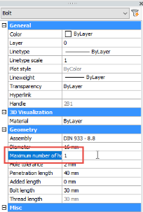
The following properties for profiles, plates, bolts and views were added :
Maximum number of holes per bolt.
This is important for galvanization holes :
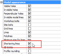
Show or hide shortening lines in views.
This option gives clearer shop drawings, the counterpart setting exists in the workshop settings :
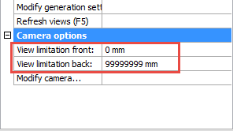
When the view has no camera, the view falls back to it’s simple front/back view limitation. This is rarely used but it is adjustable now :
Allows per-entity visibility of grating :
Allows creation and modification of surface treatment from within OPM.
This will only be available in BricsCAD for now :