Command : S3d_VisibilityMgr
 This command opens a window that can remain open.
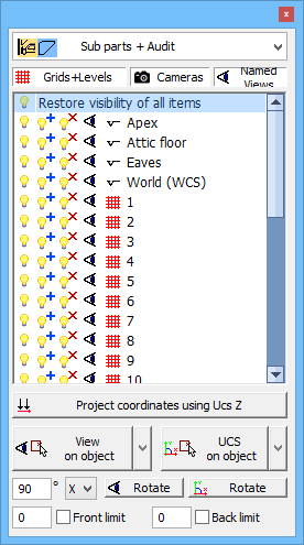
The window contains a set of tools that help you to :
- change the color of all elements
- hiding elements
- change the view
- change the Ucs
We review the purpose of each item in the window :

This list shows the available color styles for Parabuild objects. Change the style if you want the elements to follow the layers, or if you want the welded elements in a striking color (green and blue) or if you want the clashing elements in a striking color (yellow).

Only those object types that have been activated here will be shown in the list below.
In this list the levels, grid lines and cameras that exist in the drawing are shown.
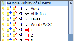
 If you click on the lamp next to fe grid A, then all elements in the drawing will be hidden except the elements that are close to grid A.
 This lamp can be used to restore visibility of all elements close to fe grid A in case they were rendered invisible by a previous operation.
 With this lamp, you can hide all elements close to fe grid A.
 Click on the eye next to an item to align the view with the level / grid / camera.
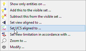
When you right-click an item in the list then you also have the possibility to change the Ucs and the view limitation according to the item, as well as to zoom in on this element in the drawing.

If you activate this button, all Z coordinates will be projected to the XY plane. The Z coordinates will thus always be 0. Note: This button affects only the Object Snap tool of AutoCAD / BricsCAD.
(This tool works by modifying the AutoCAD variables OSNAPZ and ELEVATION)
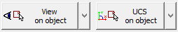
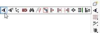
These buttons give access to a range View and Ucs tools.
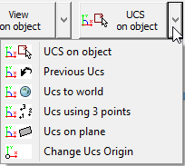
Press the button  to see all the available tools.
The last tool that you used will be shown so that you can quickly repeat the last tool.
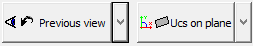

With these buttons it is possible to rotate the view or Ucs.
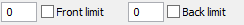
These check boxes allow you to activate or deactivate the view limitation at any time.