Add New Plan Views
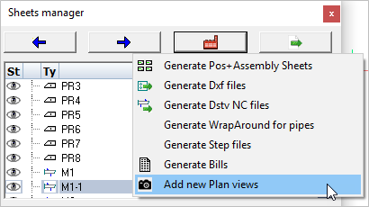
With this tool you can create a new general arrangement view based on a grid, a level, an ISO view or the current 3D view.
The new view will be drawn on a new 2D sheet if no sheet is currently active.
Activating this command will open the Creating Plan views dialog. Here you may select which view(s) to generate by checking one or more items in the list.
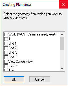
By selecting multiple views you will be prompted to select the position where each view is to be drawn. Unless you've planned exactly where each view is to be positioned within the sheet, this method can lead to some editing of the view placement afterwards.
Placing one view at a time may sometimes be easier. To place one at a time means repeating the Add new plan views process for each view.
After that the Format and scale dialog will appear, enabling you to set the drawing parameters:
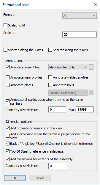
The different options in the dialog are explored below :
Format - Set the size for the new sheet
Scaled to fit - Selecting this option will set the drawing scale to fit the new view.
Scale - Manually sets the drawing scale. The scale will be set as a ratio to 1.
Shorten along the X or Y axis - When enabled, the view will be shortened in X and/or Y directions. This is usually only used on floor plans for laying out the anchors.
Annotate assemblies - When you activate this, each assembly will automatically receive an annotation. Choose the annotation style for those annotations in the drop-down next to it. More information on the annotation styles can be found at Tools for 2D drawings
Annotate main profiles - When you activate this, each main profile will automatically receive an annotation
Annotate welded profiles - When you activate this, each welded profile (non-mains) will automatically receive an annotation
Annotate plates - When you activate this, each plate will automatically receive an annotation
Annotate bolts - When you activate this, each bolt will automatically receive an annotation
Annotate all parts - When activated, parts that have the same part number will still each be annotated
Geometry size - This options works as a filter for the annotations. Parts smaller than the minimum or larger than the maximum will not receive an annotation. The length of the axis of the parts are used for this filter.
Add ordinate dimensions to the view - Checking this checkbox will add ordinate dimensions to the view.
Add dimension when the profile is perpendicular to the view - Checking this checkbox will add dimensions when the profile is perpendicular to the view - it will not add dimensions when the profile is at an angle to the view.
Back of Angle Leg / Back of Channel is dimension reference - Checking this checkbox will place dimensions from the back (Heel) of the channel or angle.
Top of Steel is reference in side views - Checking this checkbox will make the top-of-steel the reference for placing of dimensions.
Add dimensions for extents of assembly - Checking this checkbox will add O/All dimensions to the view.
Geometry size Minimum - This options works as a filter for the dimensions. Parts smaller than the minimum will not be dimension-ed. The length of the axis of the parts are used for this filter.