DSTV NC Settings
Settings for DSTV files may be changed from the Sheets manager / Settings / General
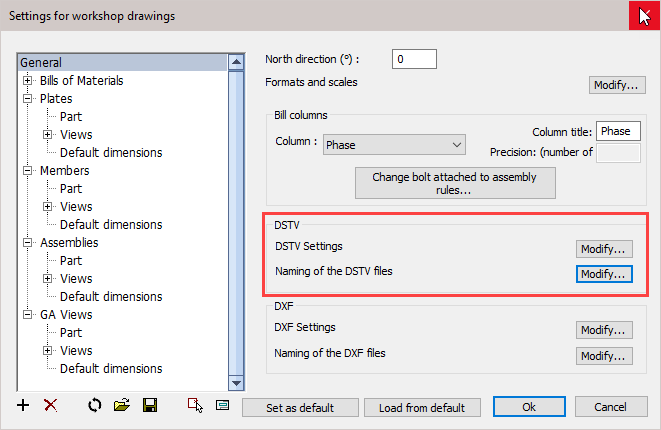
Clicking the DXF Settings / Modify button will open the following dialog where you can change the following settings :
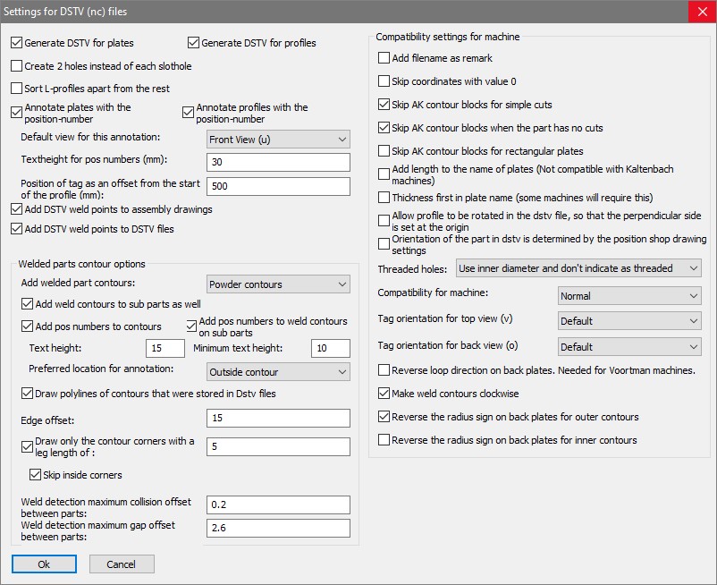
The options in the dialog box are explored below.
Generate DSTV for plates - When activated, DSTV files will be generated for plates.
Generate DSTV for profiles - When activated, DSTV files will be generated for profiles.
Create 2 holes instead of each SlotHole - If activated then Parabuild will insert two holes in the DSTV file instead of a single slothole. This is useful if the machine doesn't have a tool for creating slotholes.
Sort L-profiles apart from the rest - If activated then the DSTV files of L-profiles will be stored into a separate folder. This is useful when the L-profiles need to be done with a different machine.
Annotate plates with the position number - The machine that supports this will engrave/write the position number on the plate.
Annotate profiles with the position number - The machine that supports this will engrave/write the position number on the profile.
Default view for this annotation - Here, you can choose on which side of the part the position number should be scribed.
Text height for position numbers - Set the text height for position numbers scribed on the part.
Add DSTV weld points to assembly drawings - For each weld point in DSTV Parabuild well draw a cross in the assembly drawing.
Add DSTV weld points to DSTV file - The drill of the machine can be used to create a dot to facilitate the welder. You can find out more about this in the DSTV weld points topic.
Weld Contour types - Here you may choose between either, Punch / Powder / or Both. If you choose 'Both' then all the contours are added double to the DSTV file.
Add weld contours to sub parts as well - When you enable this, then weld contours will also be added to sub parts that are touching other sub parts. This will occur in assemblies where 2 sub parts are touching each other.
If this option is disabled, then only the subparts that are touching the main part will get a contour on the main part.
Add position numbers to contours - When you enable this, then weld contours that are placed on a main part will get a position number text.
Add position numbers to weld contours on sub parts - When you enable this, then weld contours that are placed on sub parts will also get a position number text. This will occur in assemblies where 2 sub parts are touching each other.
Text Height and Minimum text height : Here you may select the text height and minimum text height. If the part number text is located (especially) inside the contour, then a reduced height may be used. With this option, you can choose the minimum text height that the function is allowed to use for this purpose.
The Preferred location of the annotation - The default behavior is to place the annotation outside of the contour. If you choose to place it inside the contour, but the text is too large, then Parabuild will automatically place it outside anyway.
Selecting 'No Preference' will allow Parabuild to select the most suitable position.
Draw PolyLines of contours that were stored in the DSTV files - When this is enabled, Parabuild will draw a contour in the 3D model for each contour that it has written in the Dstv file. This is useful for checking the contour results, but this can clog your 3D model with lines.
Edge offset - Parabuild will trim the contour so that it does not come any closer to any edges than this offset value.
Draw only the contour corners with a leg length of : When this is active, only the corners of the contour are scribed to save machine -time with scribing work.
Skip inside corners : Inside corners will occur when an I-shaped profile is welded with the I shape to the profile. This case would have 4 inside corners. You can skip these corners with this option.
Weld detection, maximum collision offset between parts - If the welded parts collide with each other too much then the weld contour won't be added to the DSTV file.
Weld detection, maximum gap offset between parts - If the gap between the welded parts is too much then the weld contour won't be added to the DSTV file.
Compatibility settings for machine
Some machines do not follow the DSTV standard, or are based on an old version of the DSTV standard. That is why some compatibility settings are necessary in order to support as many machines as possible. Only change these settings if you are experiencing problems with reading the DSTV files in your CNC machine.
Add filename as remark - Some machines expect this, and it does no harm.
Skip coordinates with value 0 - Some machines do not expect any values with value 0 in the DSTV file.
Skip AK contour blocks for simple cuts - Some machines always need the AK block, others don't support the AK block at all.
Skip AK contour blocks when the part has no cuts - See above
Skip AK contour blocks for rectangular plates - See above
Add length to the name of plates - Normally the plates receive a name such as PL150x10. But some machines also expect the length in this name, so it will become PL150x10*200.
Thickness first in plate name - Some machines will require this
Allow profile to be rotated in the DSTV file so that the perpendicular side is set at the origin
Orientation of the part in DSTV is determined by the position shop drawing settings
Reverse loop direction on back plates - This is needed for Voortman machines
Make weld contours clockwise
Threaded holes
Compatibility for machine - These are a collection of changes to the standard that some old machines need
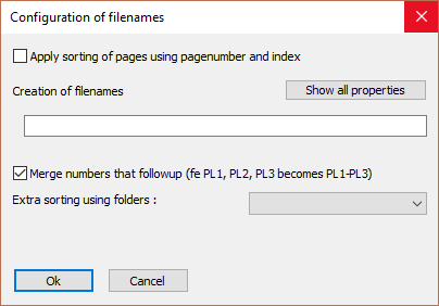
Clicking the DSTV Settings / Naming of the DSTV files button will open the following dialog where you can change the following settings :