DXF Settings
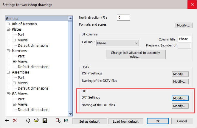
Settings for DXF files may be changed from the Sheets manager / Settings / General

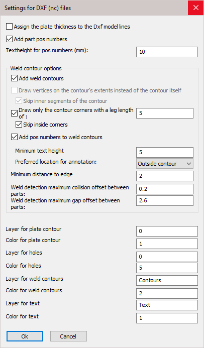
Clicking the DXF Settings / Modify button will open the following dialog where you can change the following settings :

The options in the dialog box are explored below.
Assign the plate thickness to the Dxf model lines - When active, the thickness of the plate will be assigned to the model lines in the dxf files. This creates a semi 3D model and the machine can know the required thickness of the plate this way. Some machines can't read the dxf file when this option is active.
Add part position numbers - The position number of the plate will be added as text to the DXF file so that the machine can engrave it on the plate.
Text height for position numbers - Set the text height for position numbers on the part.
Add weld contours - When active, the weld contour options become visible.
Draw only the contour corners with a leg length of : When this is active, only the corners of the contour are scribed to save machine -time with scribing work.
Skip inside corners : Inside corners will occur when an I-shaped profile is welded with the I shape to the profile. This case would result in 4 inside corners. You can skip these corners with this option.
Add position numbers to weld contours - Wen active, position numbers will be added to weld contours.
Minimum text height - Set the minimum text height for the position numbers of the contour. Parabuild will deviate from the standard text height in order to fit the text in places without much room, but will not use a text height below this value.
Preferred location for annotation : Normal behavior is to place this annotation outside of the contour. You can choose inside of the contour, but if the text is too large to fit in the contour then it will be placed outside of the contour.
Minimum distance to edge - Set the minimum distance that should be kept between the text and the edge of the plate
Weld detection, maximum collision offset between parts - If the welded parts in 3D collide with each other too much then the weld contour won't be added to the DSTV file.
Weld detection, maximum gap offset between parts - If the gap between the welded parts in 3D is too much then the weld contour won't be added to the DSTV file.
* The remaining options allow you to set the layers and colors of the different line types and texts.
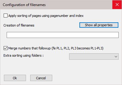
Naming of the DXF files button will open the following dialog where you can change the following settings :

