Objects to be copied from 3D to 2D views
This dialog box allows us to decide which 3D objects are added to the 2D view.
We can also configure how the translation from 3D to 2D should be done.
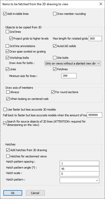
In this dialog box you can change the following options :
Add invisible lines - On workshop drawings, these lines should always be drawn. But on 3D views or GA views, the invisible lines will quickly overcrowd a view.
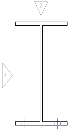
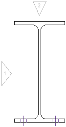
Draw member rounding -
|
|
Example 2D view with member rounding disabled |
Example 2D view with member rounding enabled |
Grid lines - Enable this option to copy grid lines to the 2D view
Project grids to higher levels - When enabled, the grid lines on the 'floor' will be copied to higher levels, even if the floor falls out of scope of the view.
Max length for rotated grids - Thanks to this option, elevation views will get grid lines.
Use this option to set the size of these 'rotated' grid lines.
Set this value to 0 to disable grid lines on elevation views all together.
Grid line annotations - This option causes the grid lines to automatically get grid line annotations on the view.
AutoCAD solids - When enabled, AutoCAD 3D Solids will be shown in the view
Draw span symbol on gratings - When enabled, grating panels will get a span symbol on 2D views. The span symbol indicates the direction of the load bars : 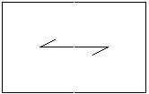
Workshop bolts - Typically, workshop bolts are shown on both the shop drawings and on the GA views
Site bolts - Typically, site bolts are not shown on the shop drawings
Draw Axis for bolts - When enabled, a red axis will be drawn for all bolts
Lines/Polylines - When enabled, lines/polylines that are drawn in 3D will also be copied to the view.
This option has no effect on workshop drawings because the workshop drawings are not based on a camera. Instead they work based on a part number filter.
Minimum size for lines - If a line is smaller than the size entered here, then the line will not be copied to the view. This option was created to overcome performance problems that happened with large drawings that contain many small lines. 2D drawings that act as an underlay will often contain many of these lines.
Draw axis of members - This option will draw the red axis line for members.
Use faster but less accurate 3D models - If you activate this option then the Parabuild 3D models will be used for the generation of the 2D views. Arcs will be drawn tessellated with short straight lines. Use this option only if you are experiencing difficulties with the option deactivated.
Search for source objects of 2D lines - This option must be activated for measuring of levels, for measuring shortened view and for the adjusting of dimensions and annotations when the view is refreshed. Thanks to this option the dimensions are measured in 3D, not in 2D.
Hatches - When enabled, all of the parts that are cut off by the view limitation of the camera will receive a hatch.
Use the additional options to configure the hatch's appearance.