The Coordinate System
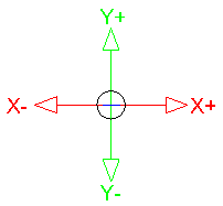
Every point in an CAD drawing file can be identified by its X,Y,Z coordinates. When viewed in plan, the X axis will pass from left to right, with movement to the right given as a positive (+) value, and to the left, a negative (-) value.
The Y axis will pass from top to bottom, with movement up given as a positive (+) value, and down as a negative (-) value.
The Z coordinate value will be 0.0 This system of coordinates is referred to as the World Coordinate System, or WCS.
|
|
2D Coordinate system |
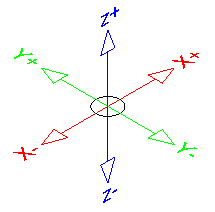
3D Coordinate system |
Coordinate input
The most direct way to enter points precisely is to type numbers with the keyboard. CAD uses these keyboard coordinate entry formats:
- Absolute Cartesian: e.g. 20,40,60
Values:
X = 20
Y = 40
Z = 60
- Relative X,Y,Z coordinates e.g. @37,-25,50 (The @ character defines coordinates relative to the last point (x = 20, Y = 40, Z = 60))
Values:
X = 37
Y = -25
Z = 50
- Relative polar coordinates e.g. @25<45 = (@distance<angle)
Values:
@25 = distance from the last point
<45 = Angle
User Coordinate Systems
You can define an additional coordinate system to more easily create drawings. This Non-World coordinate system, known as a User Coordinate System or UCS.
Why would you want to diverge from the standard WCS? Well, the most common reason is that its much easier to calculate and enter coordinates if they're based on the plane you want to work on in 3D.
Suppose that you're modeling an old-fashioned, wedge-shaped rubber doorstop and you want to add the manufacturer's logo to the sloping surface of the wedge. It isn't easy if you stay in the WCS, but AutoCAD lets you set a new UCS based on that sloping surface. After the UCS is made current, you draw in it just as you draw in the WCS.
Although originally intended for 3D work, a UCS can be useful on either two dimensions or three. The WCS assumes that the north direction is straight up, but you may be working on a building layout where one wing is at a 37.8 degree angle to the other.
No problem: Simply create a UCS thats aligned appropriately. You can look up this process in the on-line help system, but heres a quick hint: Click the UCS icon in the lower-left corner of the screen to make “grips” appear at the origin and the ends of the axis indicators. Then drag the icon by its grips to set a new UCS.
DRAW BY NUMBERS
You're CAD system will locate absolute X,Y coordinates with respect to the 0,0 point of the drawing — usually, its lower-left corner. AutoCAD or BricsCad locates relative X,Y coordinates and relative polar coordinates with respect to the previous point you picked or typed.
You will see how CAD uses all three coordinate formats to draw a pair of line segments that start at the absolute coordinates 2,1, and then move to the right 2 units and up 1 unit (@2,1) relative to the first point, and then (relative to that point) move 2 units at an angle of 60 degrees (@2<60).
Note in particular how the first two coordinate pairs use the same numbers (2,1) but the second pair defines a different point because of the leading @ symbol.
You can find out the X,Y location of the cross-hairs by moving them around in the drawing area and reading the coordinate values at the left end of the status bar. The X,Y coordinates should change as you move the cross-hairs. If the coordinates don't change, click the drawing coordinates area until you see Coordinates on in the command line.
If you're using the full version of AutoCAD, you may have noticed that three numbers are at the left end of the status bar. AutoCAD is showing you the X,Y coordinates of the cross-hairs and the current elevation. However, in 2D drafting, the Z value is 0, so you can continue calling them X,Y coordinates.
Although it isn't apparent at first, AutoCAD has, in fact, four coordinate display modes. Clicking the coordinates readout cycles through these modes:
- Off - (<Coords off>): The status bar coordinate readout is dimmed, and the coordinate values don't update until you pick a point.
- On - showing X,Y coordinates (<Coords on>): The coordinate readout appears black, and the absolute X,Y coordinates update continuously as you move the cross-hairs. If no command is active, clicking the coordinates readout alternates between this mode and <Coords off>.
- On - showing polar coordinates (<Coords on>): This mode, which displays distance and angle relative to the last point picked rather than absolute X,Y values, appears if a command is active and AutoCAD is waiting for you to pick a point.
- On - showing geographic coordinates (<Coords on>): This mode displays coordinates as latitude and longitude values, but it can be used only after you set the drawing's geographic location with the GeographicLocation command.
If you start a command such as Line, pick a point, and then click the Coordinates area a few times, the display changes from coordinates Off to live absolute coordinates to live polar coordinates. Displaying live polar coordinates is the most informative mode most of the time.
If you're working in AutoCAD’s architectural or engineering units, the default unit of entry is inches, not feet. Here are some guidelines for entering numeric values when you work with feet and inches:
- To specify feet, you must enter the apostrophe (′) symbol for feet after the number:
6′ is 6 feet.
- To separate feet from inches, enter a dash:
6′-6″ is 6 feet, 6 inches.
- When you enter coordinates and distances, both the dash and the inch mark are optional:
6′6″ and 6′6 are the same as 6′-6″.
- To type a coordinate or distance that contains fractional inches, you must enter a dash — not a space — between the whole number of inches and the fraction:
6′6-1/2 (or 6′-6-1/2) represents 6 feet, 6-1/2 inches.
- To enter partial inches, use decimals instead:
6′6.5 is the same as 6′6-1/2″ to AutoCAD, whether you're working in architectural or engineering units.