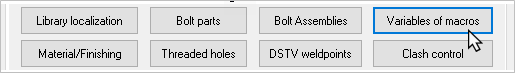
Variables of Macros
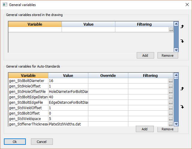
In this dialog box we can influence the variables that are used by the Macro standards.
The purpose of the macro standards is to change the macros default values to some sensible values that are dependent on the base profiles of the macro.
The Macro standards is a tool that is run automatically on each macro that is inserted from the library using any of these commands :

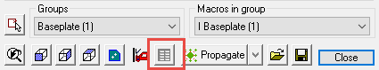
It is also possible to run the standards on a macro manually, with this button in any macro dialog box :
You can influence the standards by changing the value of a variable in the below dialog box. The changes you make to the lower list of variables apply to the system, so they apply to all projects you draw.
However do not remove variables; this is preserved for people who extend the standards.
Each variable points to a specific setting in one or more connections. It is possible that a variable has an effect on one connection, on a group of connections or on all connections.
We cannot explain all the available variables in this manual, but we will explain a select few as examples:
gen_StdWeldOffset : Determines the distance that is kept between two welded objects. This setting applies to all connections.
gen_StdBoltOffset : Determines the distance that is kept between two bolted objects. This setting applies to all connections that contain bolts.
gen_StdHoleOffsetFile : This variable contains a filename as its value. In the file itself you can make changes to influence the hole tolerance. See the next chapter for more information.
gen_StdHoleOffset : The (radius) tolerance of the hole of a bolt. This setting has an effect on all connections that contain bolts. However it only applies when the variable gen_StdHoleOffsetFile does not contain hole tolerance information for a certain diameter.
gen_StiffenerThicknessesFile : The variable refers to a special file that contains multiple plate thicknesses and widths. From this file a plate thickness will be chosen for the stiffener.
If you the file "\Pb_Lib\PlateStdWidths.dat", then you can determine the available plate thicknesses and widths. This will not only be used by the standards, but also to assign names to plates, for example:
If P10x160 is a standard size, then Parabuild will automatically choose P10x160-143 for the name of a plate that measures 143 to 160.
Files
A part of the standards variables refer to a file. You will find these files in the following location on your computer:
\Parabuilld\Pb_Lib\Connection Standards\Data\
The .dat files you find here can be modified using Notepad.
The contents of the file HoleDiameterForBoltDiameter.dat looks like this:
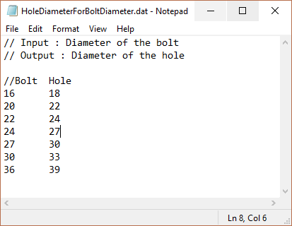
The lines that start with “//” are comments. They have no effect on the workings of Parabuild.
The purpose of each file is explained in these comment lines.
The purpose of HoleDiameterForBoltDiameter.dat is to choose a hole diameter for each bolt diameter.
If you want to add a new diameter M12, then you would add the following line:
12 14
Between the numbers 12 and 14 you should type a TAB character. Columns are separated this way.