Export BIM to File
Command - PrB_Export
With this command you can export the current Parabuild drawing to a range of file types that AutoCAD cannot write directly.
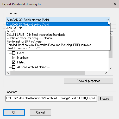
The following file types can be written:
AutoCAD 3D-Solids drawing
Will export to an AutoCAD 3D-Solids (DWG) file so that each Parabuild part will become a 3D Solid without any built-in intelligence.
Elements to export:
Template for bolts - Default templates - M%PbColBoltDiameter% and %PbColBoltAssemblyNorm%
Template for plates and members - Default templates - %PbColPosNumber%, %PbColMarkNumber% and %PbColName%
Acis .SAT file
This export method is comparable to the 3D-Solids drawing, but the .DWG file is not written. This facilitates the compatibility with software that does not recognize the DWG format.
Elements to export:
Template for bolts - Default templates - M%PbColBoltDiameter% and %PbColBoltAssemblyNorm%
Template for plates and members - Default templates - %PbColPosNumber%, %PbColMarkNumber% and %PbColName%
Ifc 2x3
Allows you to deliver the Parabuild drawing with BIM data to the client for checking and planning purposes.
Allows you to write files that are readable in Revit or ArchiCAD, with BIM data. It is used widely in the EU.
Elements to export:
Add profiles with a curved path - This should be disabled if Autodesk 'Advance Steel' will be used to read the file.
Use counter clockwise PolyLines for sections - This should be enabled if Autodesk 'Advance Steel' will be used to read the file.
CIS/2.1 LPM6 - CIM Steel Integration Standards
This format is used widely in the US. It has been tested to work together with CADWorx Structure. The format is not actively being expanded anymore, and if possible it is recommended to switch to Ifc.
WireFrame model for analysis software
Used for exporting the Wire-frame model in DWG format - not widely used.
Elements to export:
Template for plates and members - Default templates - %PbColPosNumber%, %PbColMarkNumber% and %PbColName%
KISS format for ERP software
The KISS format (Keep It Simple Steel) is a format for exchanging construction data with ERP/MIS software.
Elements to export: Also export field bolts : Shop bolts are always exported
Export nuts and washers : Nuts and washers get separate 'detail parts'
Also export labor info : Will calculate and export labor data for all holes, cuts and burns
Allow accumulation of labor : Should normally be disabled: according to KISS specification the counts should be per piece. But Kiss files written by 'Tekla structures' are accumulated so that is why this is available as an option.
For the main part, use the assembly number instead of the main part's position number
Export type - Options : Estimate / Advanced bill / Final bill / Revised bill / Change order
Sequence template : Optional, to make the sequence field a combination of phase&sequence. Currently supports %Sequence% and %Phase% ex: "%Sequence% - %Phase%"
Section name column keywords : Columns with these keywords will be used for the section shape's name. These keywords are accessible in the profile section tables.
Assembly number for sheet name when the assembly does not have a shop drawing : When no sheet was found with this assembly on it, the number could serve as a good place holder (default on)
Default drawing number when assembly has no shop drawing : This is used when the option 'Use assembly number for sheet name' is not active
Detailed list of parts for Enterprise Resource Planning (ERP) software
This will generate a simple text file (.txt) that contains a complete list of all parts in the 3D model. All of the data fields that Parabuild has for the parts are also stored.
It can be used for ERP software that only supports reading of simple text files.
Steel3D drawing for versions 7.0 until 7.2
This export allows you to save the drawing to an older version of Parabuild, but with the loss of some data.
BIM stands for Building Information Modeling. What does that mean?
In short: BIM is keeping the important information of a 3D Model, and not only the geometry. For example a beam is not only a volume existing of planes and lines, but it has a name, material, welding data, position number, etc... These data are what we call BIM data. Parabuild saves this data in the drawing together with the geometric data.
BIM data can be exchanged between different application with the help of the IFC format.
Only the IFC format supports exchanging of BIM data.
The other formats support only the exchanging of geometry.