Measure distance between 2 sub-geometries
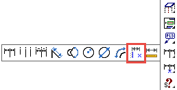
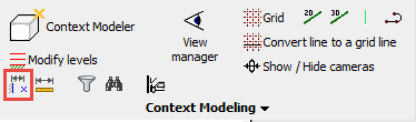
Command - Prb_Measure
With this command, you can measure the distance between 2 (sub) geometries.
The measurement will stay visible in the drawing after the command, and the value will be updated when one of the sub-geometries has changed.
The following sub-geometries are currently supported for measuring the distance between :
- Points
- Lines
- Circles
- Planar surfaces
You can use any combination of these geometries, for example line vs point or plane vs plane.
The command will ask you to select the 2 sub-geometries, after which the distance is immediately drawn on screen.
This command will actually create a new macro to do the measurement.
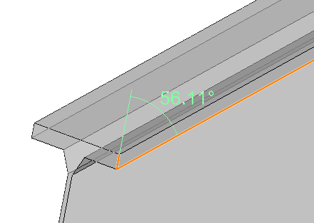
The measurement will always occur relative to the selected geometry.
This makes measurements on sloped geometry effortless.
By choosing the right geometry, we can do a lot of different measurements with just a few mouse clicks.
We can usually achieve the best measuring result by measuring between a planar surface and a point geometry.
Here are some examples of how choosing the right geometry can influence the measurement.
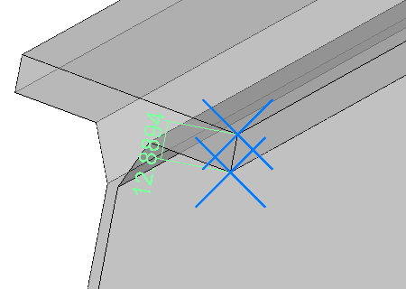
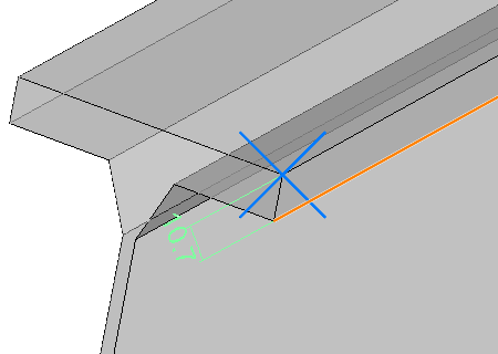
This is a profile with a sloped ending cut.
Measurement between 2 points. |
Measurement between a line and a point. |
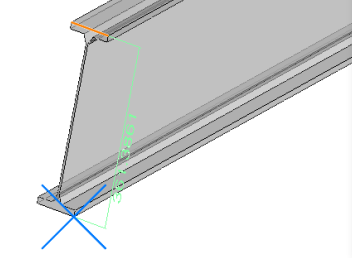
Measurement between a line and a point. |
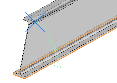
Measurement between a plane and a point. |
Measurement between 2 lines that are not parallel. |
The location of the new measurement value may not always be that obvious, especially when measuring between 2 large geometries.
The value is usually drawn in the middle of the selected geometry.
Sometimes the dimension may be drawn inside a part.
Changing the visual style to X-Ray or 2D wireframe will make the dimension visible in those cases.