Smart Copy Settings
Command - PrB_AutoApplySettings

With this command you can define how the function that copies macros must react during the selection procedure. The copy function is among other things started when we obtain a macro from the library. You must define these options on the source macro (the macro that resides in the drawing in the library).
The new, unconnected base profiles that the draftsman selects are compared to the base profiles of the macro from the library. With the aid of the options set with this command it will be decided firstly if the copy operation is possible. If copying is possible, then the order and the location of the objects that you select in this command determines how the macro will be copied.
The base defining objects of the macro
This smartcopy command works on macros that use profiles as base (defining) objects.
However, it is also possible to use points and Parabuild plane objects as base objects.
When a point or a plane is used by the macro you will also have to select them in the right order and this command will ask for the name of the points and/or planes. The name is displayed when the macro is inserted so that the user knows what point or plane to select in the correct order.
The Smart copy settings command stores the settings that are needed for inserting the macro from the library, and also for the Smart Copy command.
Do note that the Smart Copy command is not yet as powerful and does not support making copies of macros that use several of these points and planes. It only supports a single plane. The multiple points/planes feature only works when inserting the macro from the library.
Using the command
When starting this command you are first asked to select the macro of which you want to adapt the options. These options are stored inside each macro separately.
Afterwards you are asked to select the base profiles of the macro one for one.
The order in which you select the base profiles will also later determine the way the macro will be copied: for example an haunch connection: you select first the column and then the beam. When this macro is then being copied somewhere else then one must also select first the column and then the beam so that the connection will be oriented correctly.
Sometimes not only the order in which you select the base profiles matters, but also the position on the profile that you indicate can play a role for some connections. A bit further we explain this with some examples.
After you have selected all base objects, a dialog box with some options will appear :
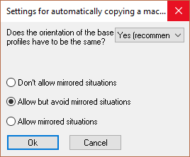
We will explore the options in this dialog box :
Does the orientation of the base profiles have to be the same?
If you enable this option, then the orientation of the base profiles of this macro will be compared with the orientation of the new base profiles and copying will be refused if the orientation differs too much.
This option must always be enabled except for some special macros that allow an orientation difference.
Don’t allow mirrored situations
The macro will never be copied if the new situation would be a mirrored macro.
Example: A connection with a U profile as base profile.
Allow but avoid mirrored situations
Avoid mirrored situations if possible, but mirror if it cannot be copied differently.
Allow mirrored situations
Always allow mirrored situations.
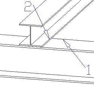
The following connection is an example where mirrored situations play a key role and it also explains the importance of where you select a base profile.
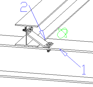
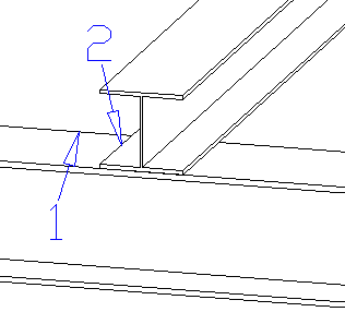
The above image is the image of the macro source itself (the drawing that resides in the macro library). The indicated points 1 and 2 were clicked in the Macro Smart copy settings command. The bottom profile is therefore the first; the upper is the second base profile. The above image only illustrates the settings of the source macro, because it influences the way the macro will be copied.
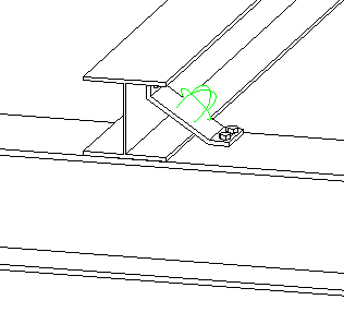
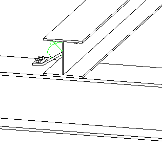
With the following four scenarios we illustrate what happens if during the copy operation of the above connection, the base profiles are indicated on other locations.
For each scenario the left image shows the selection that was made for copying the macro. The right image is the result after the macro was copied with those selections.
Scenario 1:
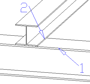
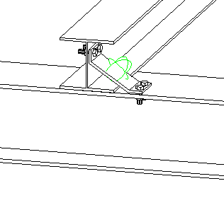
The result of this scenario is no surprise: the base profiles were selected on exactly the same spots as those of the macro source. The macro is copied to exactly the same place as the source macro.
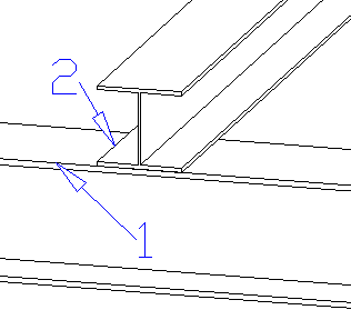
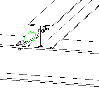
Scenario 2:
In this scenario the first base profile was selected on another spot, on the other side of the upper flange. The result is that the bent plate is also placed on that side of the flange. The bent plate was mirrored over 1 axis.
Scenario 3:
In this scenario the second base profile was selected on another spot, on the other side. Again we get a mirrored plate but at the opposite side of the second profile.
Scenario 4:
In this last scenario both the first and the last base profile were selected on another spot. The result is a double-mirrored plate.
As you can see, some macros can be copied in a lot of ways. With other macros, such as a haunch or an apex connection, only the order of the selection matters.