Version 5.1
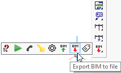
Export to KISS Format
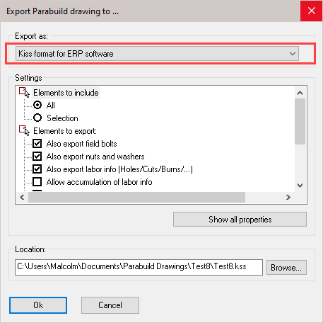
The KISS format (Keep It Simple Steel) is a format for exchanging construction data with ERP/MIS software.
The new file format can be written with this tool :
Here's a short explanation for each option :
Also export field bolts : Shop bolts are always exported
Export nuts and washers : Nuts and washers get separate 'detail parts'
Also export labor info : Will calculate and export labor data for all holes, cuts and burns
Allow accumulation of labor : Should normally be disabled: according to KISS specification the counts should be per piece. But Tekla Kiss files are accumulated so that is why this is available as an option.
Sequence template : Optional, to make the sequence field a combination of phase&sequence. Currently supports %Sequence% and %Phase% ex: L"%Sequence% - %Phase%"
Section name column keywords : Columns with these keywords will be used for the section shape's name. These keywords are accessible in the profile section tables.
Use assembly number for sheet name when the assembly does not have a shop drawing : When no sheet was found with this assembly on it, the Assembly number could serve as a good place holder (default on)
Default drawing number when assembly has no shop drawing : This is used when the option 'Use assembly number for sheet name' is not active
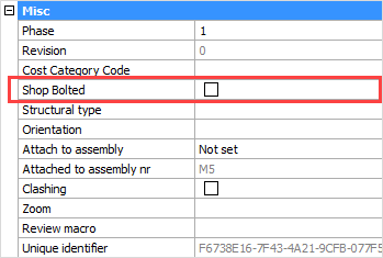
Shop Bolts
If you enable this bolt property, then the bolt will be drawn on the assembly drawing.
The bolt will act as if it is welded to the assembly.
This property will also influence the number of the assembly.
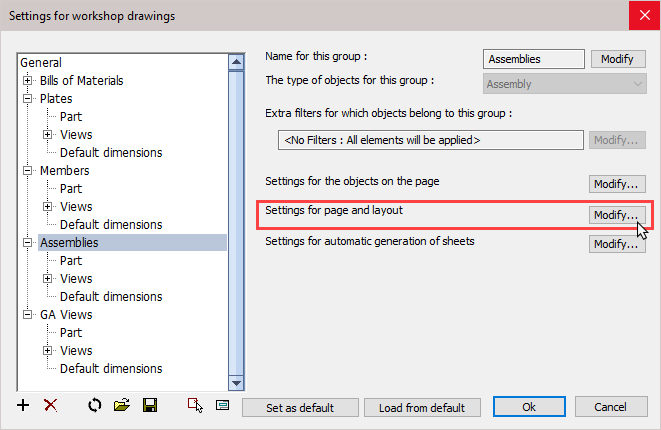
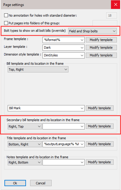
Add Bolts bill on assembly drawings
A new secondary bill can be added to the shop drawings. By default, this is a bolts bill on the assembly drawings.
You can change the bill template file, and also the types of bolts to be inserted here :
Influencing to which assembly a bolt is attached
A bolt is always attached to 1 reference assembly, even if it connects 2 or more assemblies together.
We shall call this the reference assembly of the bolt.
This reference assembly is important to have because it will determine on which assembly drawing the bolt will appear.
(a bolt will never appear on 2 assembly drawings to avoid counting the bolt more than once)
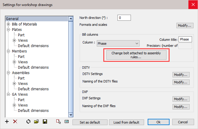
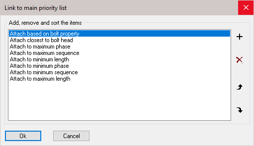
With this priority list you can influence the automatic assignment of reference assembly of all bolts - the list is ordered according to priority.
you can add, delete, and sort all items in the list.
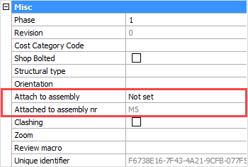
In exceptional cases where the automatic choice taken by Parabuild is not as desired, it is still possible to manually set the reference assembly in the properties of the bolt:
Attach to assembly - In this property we can choose the assembly from the drop-down menu: Closest to bolt head or Closest to Bolt end
This will effectively override the main priority list
Attached to assembly nr - This will indicate to which assembly the bolts are attached
Erection Sequence Property
All plates, profiles and structures now have a new sequence property
The sequence of a part has the following capabilities:
- The reference assembly of a bolt can be determined by the sequence number of the assemblies
- The sequence is exported to KISS file
- It should be available in bills when you make the columns : %PbColSequence% (doesn't work yet
- A planning tool for erection is a future addition
New features for Dxf files
The automatic location of text on the plate is now much better : It is drawn close to the contours, and making sure that the text does not collide with contours.
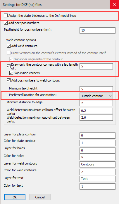
Here we outline the new options that were added to the Dxf dialog box :
Assign the plate thickness to the Dxf model lines : When active, the thickness of the plate will be assigned to the model lines in the dxf files. This creates a semi 3D model and the machine can know the required thickness of the plate this way. Some machines can't read the dxf file when this option is active.
Draw only the contour corners with a leg length of : When this is active, only the corners of the contour are scribed to save the machine some time with scribing work.
Preferred location for annotation : Normal behavior is to place this annotation outside of the contour. You can choose outside of the contour, but if the text is too large to fit in the contour then it will be placed outside of the contour anyway.
Skip inside corners : Inside corners will occur when an I-shaped profile is welded with the I shape to the profile. This case would have 4 inside corners. You can skip these corners with this option.
New features for Dstv file generation
- Countersunk and blind holes are now implemented in Dstv (509)
- The automatic location of text on the parts is now much better : It is drawn close to the contours, and making sure that the text does not collide with contours.
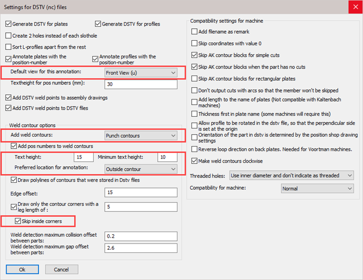
Here we outline the new options that were added to the Dstv dialog box :
Default view for this annotation : You can choose on which side the part's number should be scribed
Add weld contours : You can now choose between either punch, powder, or both. If you choose both, then all of the contours are added double to the dstv file.
Weld contour text height : Sets the default height of welded part numbers text (this is a separate value from the main part's number).
Weld contour minimum text height : If the part number text would fit somewhere (especially inside the contour) if it were of a smaller size, then a reduced height will be used. With this option you can choose the minimum text height that the function is allowed to use for this purpose.
Weld contour preferred location for annotation : Normal behavior is to place this annotation outside of the contour. You can choose outside of the contour, but if the text is too large to fit in the contour then it will be placed outside of the contour anyway.
Skip inside corners : Inside corners will occur when an I-shaped profile is welded with the I shape to the profile. This case would have 4 inside corners. You can skip these corners with this option
New project data for the title block in shop drawings
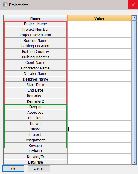
The title blocks have now received 15 fixed fields.
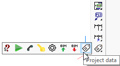
These fields can be modified in the Project data dialog box :
In this dialog box the first 15 fields are fixed and always there, no matter what the title blocks contain.
These 15 fields are used not only for filling title blocks in sheets, but also for writing project data to KISS format files for example.
These 15 fields will work across all languages. If you would change the Parabuild language then the field values will stay intact.
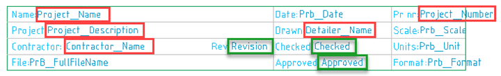
In the below image, the fixed fields are indicated in red.
When using these fields in a title block, it is possible to use the text "Project Name" or "Project_Name". Both texts will be replaced by the actual project name.
The dynamic fields are indicated in green. These fields can be entered freely.
The dynamic fields can be added by simply typing them in a title block, and saving the dwg file.
When you open the Project data dialog box, all of the title blocks that start with the current language (English*.dwg) will be loaded and all text fields are analyzed. The non-standard fields are then added to the list of fields.
New sheet properties
There are 3 new properties available for sheets
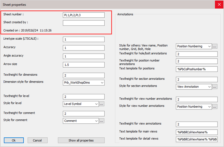
By default, the sheet number is the same as the sheet name. But this number can be changed manually.
The created on date and time is filled automatically.
All of the 3 new properties are written in KISS files.
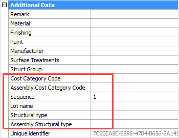
New plate / profile properties
Cost Category code : These codes are usually determined while a quote for the project is made. This code can then later be assigned to the 3D model when the project was ordered. This way the parts can be traced from estimation to production and to completion inside ERP/MIS software. This value is exported to KISS files. (PbColCostCategoryCode and PbColAssemblyCostCategoryCode)
Assembly Cost Category code: See Cost Category code
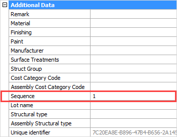
Sequence: The erection sequence of the part. This value is exported to KISS files. (PbColSequence)
Lot name: The lot that the part belongs to. This value is exported to KISS files. (PbColLotName)
Structural type: To be used in the future. For example : Bracing/Rafter/Stringer/Handrail/Post/etc.... (PbColStructuralType)
Assembly Structural type: To be used in the future. For example : Stair/Railing/etc.... (PbColAssemblyStructuralType)
Beam camber (profiles only): The camber (distance) to be used for the beam. This value influences the position number of the beam. This value is exported to KISS files. (PbColBeamCamber)
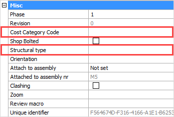
New bolt properties
Structural type : to be used in the future
Cost Category code : important for ERP/MIS software (PbColCostCategoryCode)
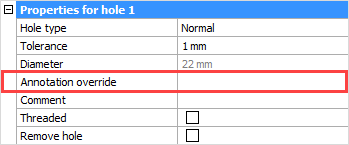
Hole annotation override
A new property was added for holes, which allows you to set a custom annotation text for a hole.
The property is only modifiable from the properties of the bolt.
This text will appear on position shop drawings
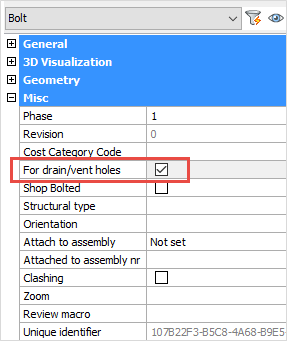
Skip holes for drain / vent holes in shop drawings
When active, all 'drain / vent' holes will not receive dimensions on the position shop drawings.
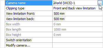
Connect view to a camera
It is now possible to connect a view to a different camera.
This is a useful tool to fix broken views
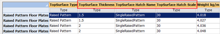
Raised pattern floor plates
The hatch pattern in the profile tables work now.
New profiles drawn with a table that has these special hatch columns will now automatically get a surface treatment on 1 face.
(this features is only supported for flat bar shapes)
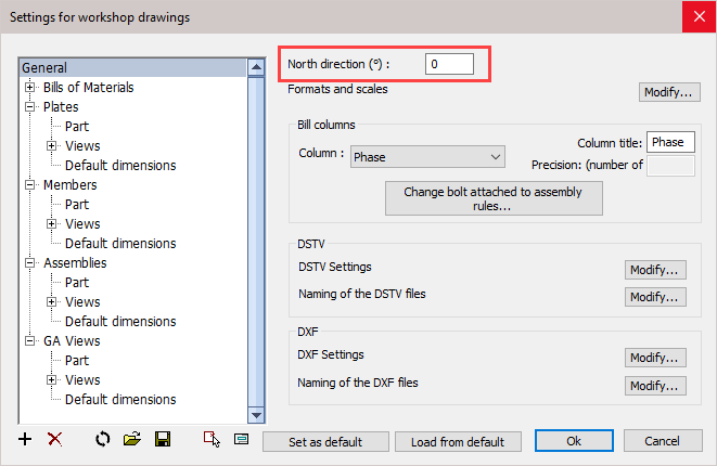
Cardinal directions for 2D drawings
The shop drawings can optionally use the cardinal directions for views (this is nothing new).
Parabuild uses the current drawing's NORTHDIRECTION variable to know this direction.
An option in the shop drawings dialog box was added to more clearly show this relation:
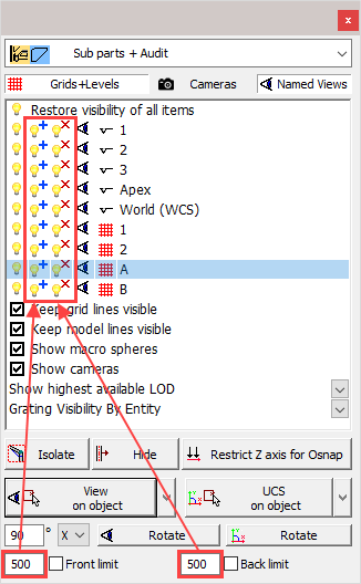
Additional visibility options
The isolate lamp buttons will now use the front/back values to determine how many parts should be isolated