Version 9.0 - Migration guide for users
Summary
These are the most important changes and additions in this release :
BricsCAD V26 is now supported
Programming API (C++)
We are introducing a new programming API for advanced customization of Parabuild.
The functions that make User shortcuts work are also exposed with this API.
For now, only the C++ programming language is supported.
To use this API simply include the header file \Parabuild\Api\PbApi.h into a .cpp file of your ObjectARX or BRX project.
There is no need to link to a library file.
This header file also includes information on how to use each function.
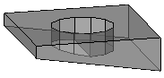
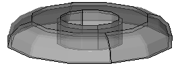
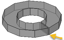
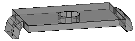
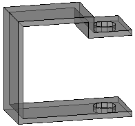
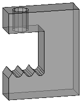
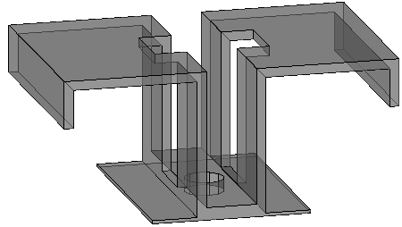
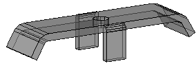
Complex bolt parts
Complex bolt parts allows us to display complex geometry to represent bevel washers, cap nuts, nylon plugs, hold down clips, and any other parts that can be drawn with extrusions (+revolves).
There are several reasons for using complex bolt parts to draw special bolt parts instead of drawing them as regular parts or structures:
- Ease of use and automation during drafting : all commands and macros that can draw bolts allow us to draw these special parts instantly and in the right location, which is an enormous time saver.
- Reports generated by Parabuild will accurately list these parts as sub parts of the bolt assembly. If they would be drawn as separate parts then they would be listed as such in the reports.
- The resources required to draw these complex parts on the graphics card, CPU, and dwg file size are significantly reduced. Parabuild uses several optimizations to reduce the resource requirements compared to normal AutoCAD/BricsCAD objects. This is particularly important when hundreds or thousands of these parts are drawn in the 3D model.
How these complex bolt parts can be created is explained in the Bolt Parts database topic.
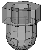
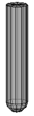
The following bolt parts were added to the standard Parabuild library of a new full installation : Bevel washer, Split lock washers, domed nuts and nylon plugs.
When you install the Parabuild version 9 update then these parts will not be installed.
That is due to the common file names of the bolt parts, so that the update does not overwrite the changes that you did to the bolts database.
You can install the bolt parts manually with this zip file which contains all the necessary files. Care should be taken when overwriting files in your library. It may be necessary to merge the .dat files manually using a simple text editor such as Notepad.
Adding Center of Gravity markings to views and CNC files
Center of Gravity (COG) marking on the view
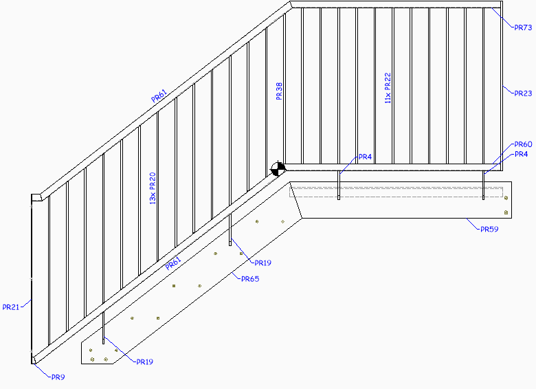
Assembly and single part views can now show the center of gravity with a symbol :![]()
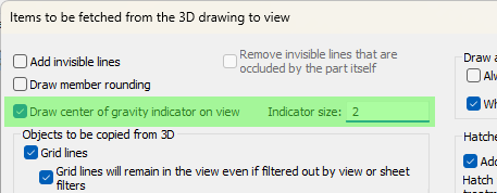
The option for activating this can be found in the Objects to be copied from 3D to 2D views dialog box :
COG marking in Dstv CNC files
The option can be activated in the DSTV NC Settings separately per profile side :
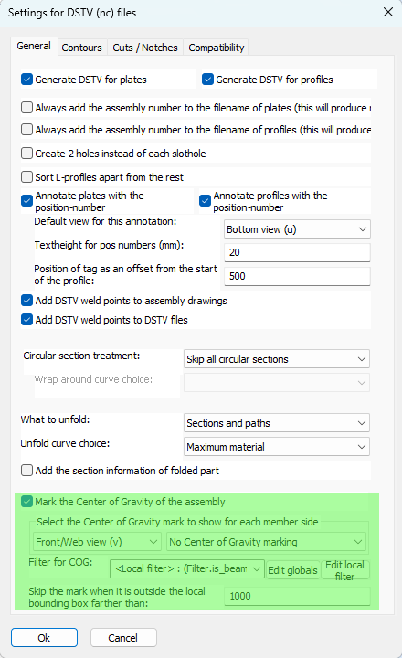
The new options are explained here :
Mark the Center of Gravity of the assembly - This option enables the Center of Gravity (COG) marking of the assembly's weight. This marking tool only works on the main part of the assembly.
Select the Center of Gravity mark to show for each member side - This option has 2 dropdowns that work in tandem.
First choose a profile side from the first dropdown, after which the Center of Gravity (COG) type for that side is shown in the second dropdown. So we can choose a different COG type for each profile side.
The following COG types are available :
- No Center of Gravity marking - This disables the COG marking for this side, for all profiles, even if the filter explained below passes.
- Add a punch mark on COG - The COG will be indicated with a mark using the tip of the drill.
- Add a scratch '<' mark (KO block in Dstv) - The COG will be indicated with a small contour in the shape of '<'. The KO type contour is used in this case, which means scratching.
- Add a powder '<' mark (PU block in Dstv) - The COG will be indicated with a small contour in the shape of '<'. The PU type contour is used in this case, which means powdering.
The COG location in Dstv files is projected perpendicularly on the member, and centered in the web/flange. The COG will thus only be informed over the length of the profile.
Filter for COG - When no filter is entered here, then the above COG markings will be applied to all profiles.
When a filter is chosen here then the above markings per side will all be applied if the profile passes the filter.
Skip the mark when it is outside the local bounding box farther than - This option allows us to skip the COG marking when it falls too much 'outside' of the member. As the COG mark is drawn in the middle of the member, it may still be drawn when the location is outside of the member. This offset allows us to choose the maximum local offset of the mark. This value is in drawing units.
Assembly COG and numbering
A new option was added to the Global settings specifically for the COG sensitivity in numbering :
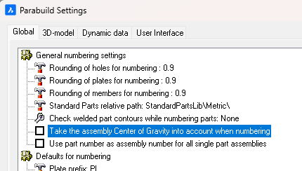
When this option is enabled, then main parts with different COG locations will receive different part numbers.
If this is disabled then 2 main parts could get the same part number even if they have different COG locations (when they are used in different assemblies). In that case, the Dstv output will still write a different file for each part but with the assembly number added to the cnc filename. Enabling this option will prevent this entire situation from occurring altogether.
Manually choosing the contour side of plate DXFs in case a plate has contours on both sides
We can now manually influence the contour side per plate that is written to Dxf files.
The following option was added to the DXF Settings for this situation :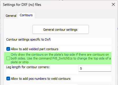
When this option is disabled then Parabuild will automatically choose the best side of the plate. When multiple parts are attached to a side then that side will be chosen. When the amount of parts is the same on both sides, then it will choose the side with the longest contours.
When this option is enabled then Parabuild will always choose the top side of the plate when both the top and bottom sides have contours.
You can use the command Switch Profile/Plate triangle direction to switch the top and bottom side of a plate or strip.
Note that for plates the long triangle is not necessarily the X axis of the plate. This triangle's orientation can be changed in the Global settings or even be replaced by a small coordinate system called Detailed Ucs icon.
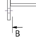
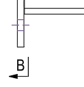
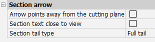
Changes to section annotations to better support the ISO and ASME styles
The following section annotation properties, which are also available in the Annotation style, will allow us to draw the section annotation in either ISO or ASME style :
|
|
ISO style |
ASME style |