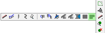
Add/Modify grating or floor plate data to a part
Add grating or floor plate data to a plate
Command - PrB_GratingOnPlate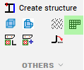
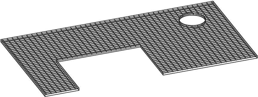
This command creates grating and floorplates based on any existing plate. The grating or floor plate geometry will then always show on the plate in 3D or 2D views - if allowed by the appearance settings of the view.
The command accepts plates, polylines, circles and strips for the selection. The polylines, circles and strips will be converted to plates automatically.
The thickness of the plate will be adjusted automatically to match the thickness of the grating data.
Adding grating or floor data to a plate has the advantage that the plate can have any size or shape, whereas the strip-based grating or floor section tables have a limited set of grating widths and thicknesses to match standard sizes available from manufacturers.
Grating or floor plate data in the 3D model can now also be modified, added, or removed from the advanced properties of the plate.
Library grating or floor plate data is configured in and retrieved from grating section tables.
We can use the grating section tables with standard widths (the width will be ignored) or you can use one of the newly added section tables that were created specifically for plates.
Section tables for plate-based grating are the same as other grating section tables except for 3 things :
- They contain a new column "Plate Name Template", which allows you to influence the plate name. When you leave this field empty then the name of the grating plate will be the plate's sizes in combination with the grating's row entry name. It is allowed to use variables in this string such as %Name% which inserts the default name of a plate, containing general sizes of the plate.
- These tables contain the width column, but this column is ignored because the width is solely determined by the plate
- The weight per length column is also ignored because the weight is calculated based on the area of the plate
How to display grating data in the 3D model
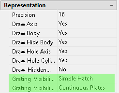
When using Parabuild to draw grating we can at any time choose whether the grating should be drawn fully detailed, approximated, or even just by a hatch or span symbol. This allows us to draw projects with large amounts of grating. If it starts to affect computer performance, then set the grating graphics to be approximated and turn it back on when it is time for checking or rendering.
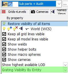
The grating appearance can be modified per part in the properties, or globally in the views manager :
Modifying grating information of existing members and plates
The grating information can be modified in the advanced properties, which is accessible from the Properties panel.
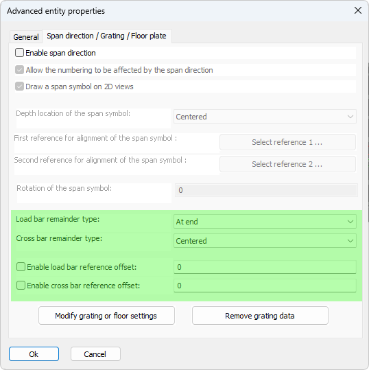
The new advanced properties are clarified below :
Load/Cross bar remainder type - Choose how the bars are distributed over the plate's width or length.
|
|
|
|
|
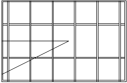
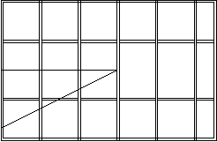
The result when the cross bar remainder type is set to Centered |
The result when the cross bar remainder type is set to At start |
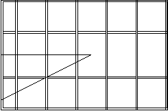
The result when the cross bar remainder type is set to At end |
Enable load/cross bar reference offset - This is the offset from the edge of the grating panel to the center of the bar
If the remainder type is set to centered then the reference offset is taken as an indication of a minimum offset.
If the edge distance is smaller than the reference distance, Parabuild will attempt to reduce the number of bars by one to increase the edge offset
If the remainder type is not set to centered: If remainder is "At start", this fixed offset will be "At end", and vice versa
No minimum or maximum is applied, so be careful as this can cause incomplete or cut grating at that side