Floors
Command - Prb_CreateProfFloors
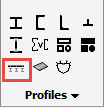
Activating this command will open the Select profile dialog - where you will be prompted to select a flooring profile.
Floor types are divided into 4 groups:
|
|
|
|
|
|
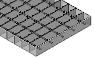
Press Lock Bar Grating |
Welded Bar Grating |
Swage Lock bar Grating |
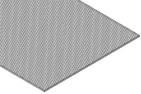
Raised Pattern Floor Plates |
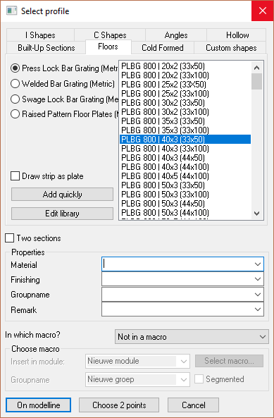
From this dialog you may select the required flooring type by selecting the appropriate radio button - the column to the right will display the value tables applicable to the selected floor type.
The value table will display the floor panel characteristics which may be interpreted thus:
PLBG 800 | 40x3 (33x50)
PLBG = Floor panel type - in this instance, Press Lock Bar Grating
800 = Standard panel width
40x3 = The bearing bar size
(33x50) = the grating opening size. 33 = the bearing bar centers, while the 50 = the transversal bar spacing
Adding and Editing floor panels in the library
Custom Floor panels may be added to the library by clicking the Add quickly button in the Select Profile dialog which will open the Add profile dialog
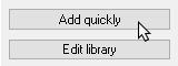
This function will add a new profile to the active Value Table.
Edit Library
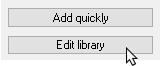
This function will open the Edit profile library dialog where the properties of specific floor panels may be edited.
For more information on editing the library, you can read the Editing the profile library topic.
Custom grating bar sections
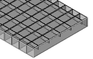
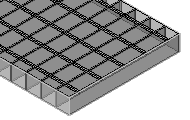
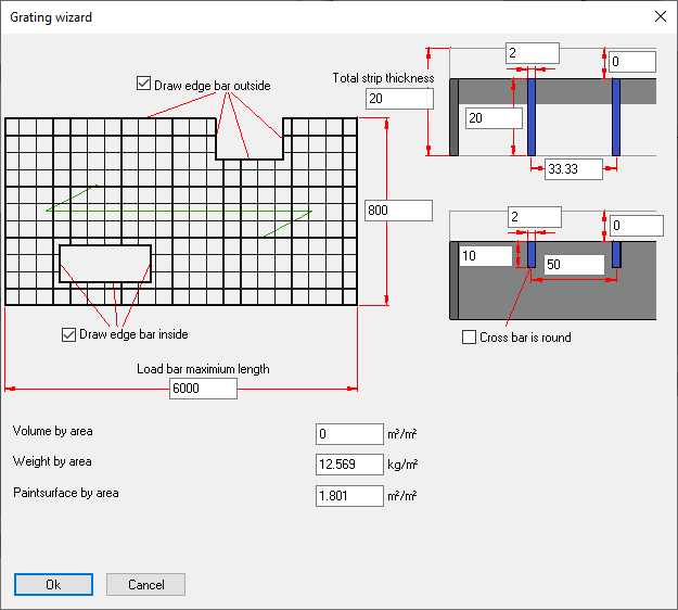
It is possible to use custom grating bar sections, for example to accurately portray pultruded grating. Custom sections will appear in both the 3D model, shop drawings and GA drawings, if configured that way in the view appearance settings.
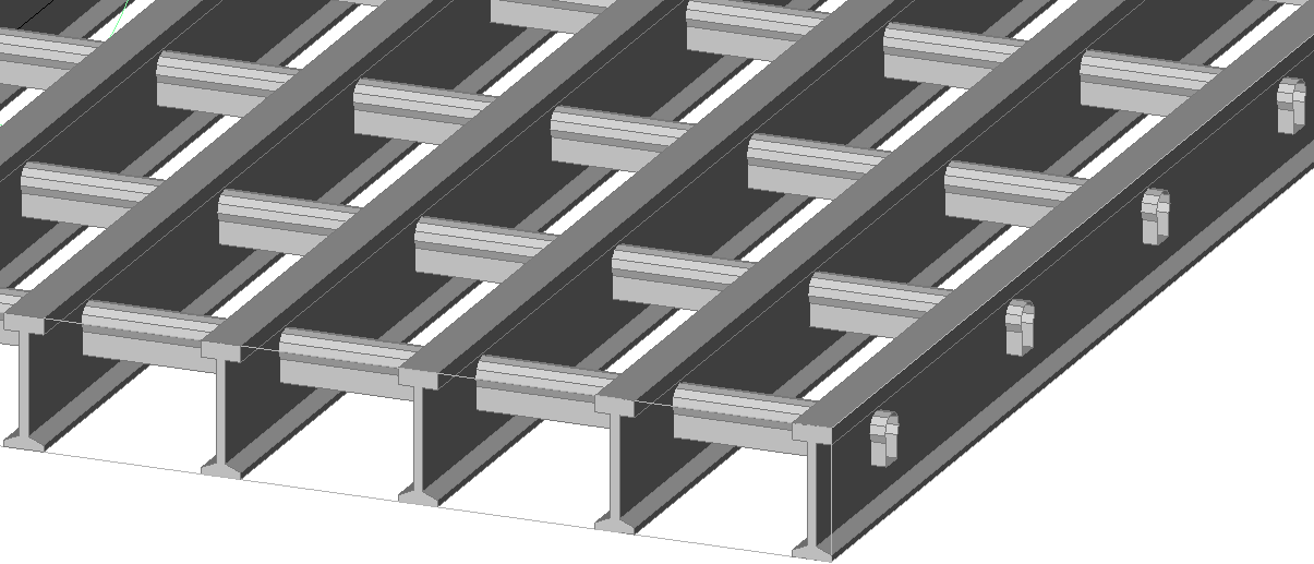
This is an example of a pultruded grating with a loadbar specified by section name, and a custom section for the crossbar specified by filename
Using section names or custom sections in grating tables
To use this feature we can add the columns with the name LoadBar Section and Crossbar Section to the grating tables :
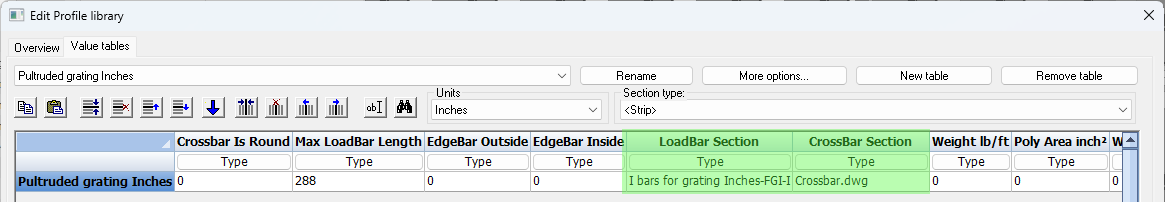
For the contents of these section fields we can choose one of the following :
- The name of a section that is defined in one of the Section tables
- The dwg file name of a Custom shape that is stored in the library
Section table for load bars
A section type called I section with flexible input was specifically added for representing the pultruded grating load bars shown above.
A section table called Grating I Loadbars was exists which uses this new section type :

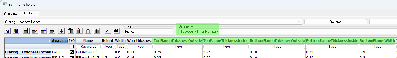
Most columns speak for themselves, but there are some special cases that need further explanation :
- BottomFlangeWidth is to allow for a smaller bottom flange (the top flange has the width of the Width column)
- ThicknessInside means the thickness of the flange at the web
- ThicknessOutside means the thickness of the flange at the outer edge
Splitting ThicknessInside and ThicknessOutside allows for flanges that are sloped on the inside such as this example.
We will not be using this section table to draw profiles so therefore this section table is by default not enabled in the Draw Profiles selection dialog box.
But the section table needs to exist nonetheless so that the grating tables can access the loadbar data from here.
Offset columns for specifying loadbar and crossbar position
The example grating tables for molded and pultruded grating contain the 4 new columns :
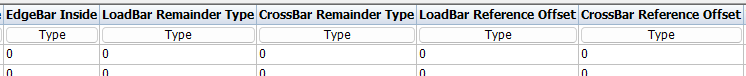
The columns are further explained :
- LoadBar Remainder Type - In this column only 3 numbers are valid : 0 = centered, 1 = at start, and 2 = at end
- CrossBar Remainder Type - This is the same as the loadbar column
- LoadBar Reference Offset - This column should contain a distance by which the bar should be moved, on the opposite side of the remainder type
- CrossBar Reference Offset - This is the same as the loadbar column