
Degrees of Freedom
The restrictions that the rules impose on a 3D-model can be seen as removing degrees of freedom of the 3D-Model.
A degree of freedom is the way an element can move in 3D.
Each rule puts restrictions on the 3D-Model. The one rule imposes more restrictions than the other. Also the type of geometry plays a role: two planes that are coincident on each other will put more geometric restrictions than two lines that are coincident. A plane means in that respect more than one line, and a line more than one point. You must therefore use as many planes as possible, because then you have to produce fewer rules and you will reach your expected result more rapidly and intuitively.
An intelligent 3D-Model should ideally be seen as having absolutely no degrees of freedom. It is possible to use a 3D Model with degrees of freedom, but this can end in unexpected results.
Imagine yourself the following scenario as an example:
You put a plane of a plate on a plane of a profile. The thickness of the plate was not defined (degree of freedom!).
When you would move the profile, the plate must move too. While calculating your macro Parabuild has a problem: does the plate have to become thicker in the distance that was moved, or will the plate be moved entirely and preserve the same thickness? In this case Parabuild will preserve the thickness. Parabuild will always try to preserve the original form of the plate, but it is not a perfect solution: Parabuild sometimes has to “gamble”, or sometimes will not be able to find a solution. To receive results that are always correct you should therefore always add rules until your 3D-model has 0 degrees of freedom.
Another example of too many degrees of freedom can be found in the Calculate all Macros topic.
Arcs in plates or polylines
Arcs (or cylinders) that are drawn in plates or in polylines are more difficult to constrain than points, lines and planes.
The main reason is the direction of the cylinder and the position of the end points of the arc or cylinder.
It is important to define the correct position of the edges, but sometimes we can't just set the distance from an outside face to the cylinder's edge, like in this example case :
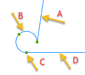
This is an example of the cylinder B getting a wrong direction after calculation. Note that the edge C is located outside of the material direction of face A
A tangent constraint does not help to resolve this case because the cylinder is tangent with both faces.
Often the original macro was calculated correctly, but appears this way after inserting it from the library. That insert operation causes direction information of the cylinder to become wrong after rotations.
We can't just set a distance constraint from face A to edge C in this case if we want to set the radius size of the cylinder B.
Instead we can use the Chirality constraint to set the edge C's direction inside face A.
It is good practice to not just set the correct inside/outside position of both edges, but also the direction of cylinder B inside face A, and cylinder B inside face D.