
Visibility Manager
Command : PrB_VisibilityMgr
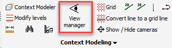
Selecting this command will open the Visibility manager window.
This dialog box may be docked by dragging it by the title bar to one of the edges of the application window.
This window contains a set of tools that will enable you to:
- Change the color of all elements
- Isolate elements
- Change the view
- Change the UCS and other tools related to the UCS
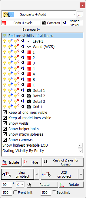

This list shows the available color styles for Parabuild objects. Change the style if you want the elements to follow the layers, or if you want the welded elements in a striking color (green or blue). Or if you want the clashing elements in a striking color (Yellow)

When one of these buttons are activated, the corresponding element types will be shown in the list below: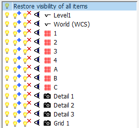
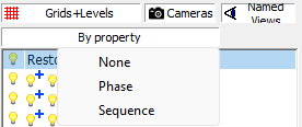
The By property button shows a pulldown that offers the following extra items :
None - This is the default and it disables the extra items
Phase - When you click on this all of the phases currently used in the 3D model will also be listed for easy isolation on each phase
Sequence - When you click on this all of the sequences currently used in the 3D model will also be listed for easy isolation on each sequence
In the list the levels, grid lines, cameras, phases, and sequences that exist in the drawing are shown if their respective button is activated.
 Clicking on the lamp next to grid 1, all elements in the drawing will be hidden except the elements that are close to grid 1
 This lamp can be used to restore visibility of all elements close to grid 1 in case they were rendered invisible by a previous lamp button operation
 With this lamp, you can hide all elements close to grid 1
 Click on the eye next to an item to align the view with the level / grid / camera
When you right-click an item in the list then you also have the possibility to change the UCS and the view limitation according to the item, as well as to zoom in on this element in the drawing.
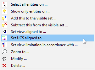
Other actions in this list like modify and delete will work on cameras and levels.
At the bottom of the list the following settings are always shown and they are explained hereafter :
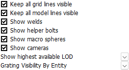
Keep all grid lines visible - When this option is enabled then grid lines will never be hidden when an isolation action is performed. This can help with giving you a sense of where on the site you are looking at when most objects are hidden.
Keep all model lines visible - When this option is enabled then model lines will never be hidden when an isolation action is performed. Model lines are lines on the layers Pb_ModelLines, Pb-ModelLines, PrB_Model, or PrB-Model. This can help with giving you a sense of where on the site you are looking at when most objects are hidden.
Show welds - This checkbox is an action by itself. When you disable this then all the 3D welds will be hidden and vice versa. The isolation actions will also honor this setting's current value.
Show helper bolts - This checkbox is an action by itself. When you disable this then all the hole helper bolts will be hidden and vice versa.
Show macro spheres - This checkbox is an action by itself. When you disable this then all the macro spheres will be hidden and vice versa. The isolation actions will also honor this setting's current value.
Show cameras - This checkbox is an action by itself. When you disable this then all the cameras will be hidden and vice versa. The isolation actions will also honor this setting's current value.
Show (highest available) LOD - This setting will only do something when you have used the command to convert general 3D Solids into Parabuild profiles prior. When you switch to LOD 200 then the converted solids will be shown and the Parabuild profiles that resulted from their conversion are hidden. When you switch to LOD 400 then the solids are hidden and the Parabuild profiles will be shown. This tool allows you to hide the converted solids without having to hide all other solids from the model. But then still allow you to see the (LOD200) solids at a time of your choosing.
Grating visibility (By Entity) - This setting applies to all Grating plates and profiles. The purpose of this setting is to reduce the clutter that grating can create in the model, but also to make the model require much less hardware resource intensive on projects with lots of grating.
This setting has the following options :
- By Entity - When enabled then the visibility is not overridden for the entire model but rather set in the properties of each part separately.
- None - The grating will not be drawn
- Span symbol - Only a span symbol that indicates the direction of the load bars will be shown
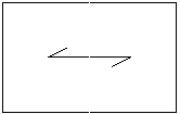
- Simple hatch - The grating will be represented by a simple hatch : 1 line per bar
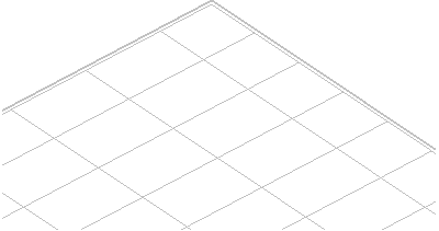
- Simple hatch see through - The grating will be represented by a simple hatch : 1 line per bar. Everything behind the grating plate is drawn as if the grating plate does not obscure anything behind it. If there are any edge bars, they are drawn in full.
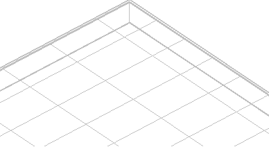
- Real hatch - The grating will be represented by a hatch that shows 2 lines per bar.
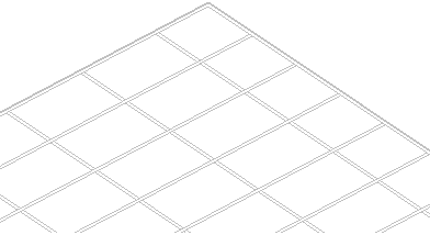
- Real hatch see through - The grating will be represented by a hatch that shows 2 lines per bar. Everything behind the grating plate is drawn as if the grating plate does not obscure anything behind it.
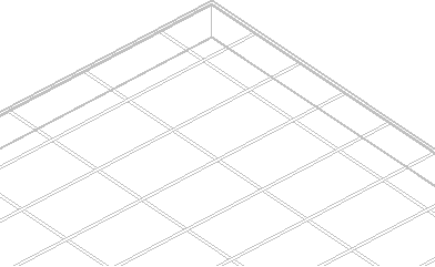
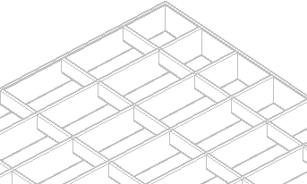
- Continuous plates - In this style the grating bars are drawn, but they are colliding with each other. This causes less lines to be drawn and the bar intersections are not exactly drawn according to drafting rules. This takes op more hardware resources if there is a lot of grating, but is still faster than the 'Realistic' option.
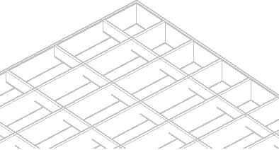
- Realistic - In this style the grating bars are fully detailed with intersecting lines where bars cross each other. This will take the most time to process (and the most amount of data that needs to be sent to the graphics card), which will be noticeable on projects with a lot of grating.

By selecting the Isolate button you will be prompted to select the objects to be isolated - press <Enter> and all other objects will be hidden.
To restore the visibility of all elements, select  at the top of the list in this dialog.

By selecting the Hide button you will be prompted to select the objects to be hidden.
To restore the model, select at the top of the list in this dialog

By activating this button, all Z coordinates will be projected to the XY plane. The Z coordinates will thus always be 0. Note: This button affects only the Object Snap tool of AutoCAD / BricsCAD.
(This tool works by modifying the AutoCAD variables OSNAPZ and ELEVATION)
This is a useful tool if you want to temporarily work in the current UCS XY plane. One can then easily draw something in a roof if the UCS was set to align with a rafter.
Do not forget to disable this button again after you're done. When this button is enabled and you're not aware of it, then your object snaps will not work as you would expect it.

These buttons provide access to a range of view options - press the arrow button to see the full range of available options.
We will explain the most important tools.
 This is a good tool because you just need to select 1 object, and the view will be oriented according to the geometry of that object. If the object has an axis then this will be the new X coordinate of the view. Otherwise it will choose the longest geometry as X axis (this tool works on any type of object).
 This tool is very powerful because we can determine with just 2 clicks which surface the view should be aligned to. As opposed to View on object this tool does not assume an X axis automatically. Instead it relies on the surface that you selected as basis for the view's new orientation (This tool only works on Parabuild objects).
 Same as View on object but in this case the UCS will be aligned to the object.
 Same as View on plane but in this case the UCS will be aligned to the surface.

With these buttons it is possible to rotate the view or UCS.

This refers to the old view AutoCAD limitation that will clip in front of and behind the current viewing point.
The downside to this old clipping tool is that it will only work well with 2D views. For this reason, it is not being used that often anymore.
The check boxes allow you to activate or deactivate the view limitation at any time.
The distances in front of the checkboxes determine how much in front and how much behind the viewing point should remain visible.
These 2 distances will also be used whenever you click on any of the isolate buttons to determine which parts should be isolated in front of or behind your target gridline or level (regardless of whether the view limitation is on or off).