AWS Weld Symbol
The Basic AWS Weld Symbol
|
|
Note! * = Fillet welds only ** = Intermittent welds only |
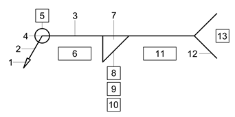
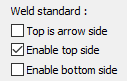
Note: Weld symbols placed under the reference line relates to welds on the arrow side of the plate being welded. Weld symbols above the line relates to weld on the far side of the plate. Weld symbols placed above and below the reference line, indicate the weld is to be placed on both arrow-side and far-side of the plate.
The following illustrations clarify this :
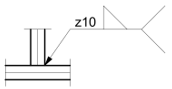
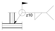
Continuous Fillet Weld - Arrow Side |
||
|
|
|
Dialog Setting |
Weld |
Weld Symbol |
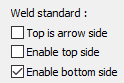

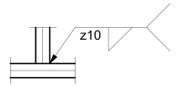
Continuous Fillet Weld - Far Side |
||
|
|
|
Dialog Setting |
Weld |
Weld Symbol |

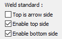
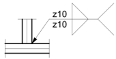
Continuous Fillet Weld - Both Sides |
||
|
|
|
Dialog Setting |
Weld |
Weld Symbol |

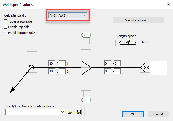
Editing the Parabuild ISO Weld Dialog
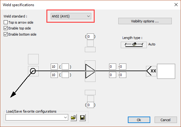
- The Arrow is at the point of the mouse pointer and should be placed at the weld position
- The Leader will stretch in compliance with the movement of the mouse pointer
- The Reference line contains all the weld information for the weld on the near side of the plate being welded
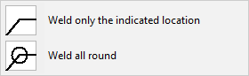
- The Weld type is to indicate whether the weld is to be only at the indicated position or all-round - select either from the dialog
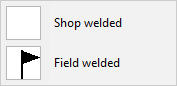
5. Shop or Field weld - select either from the dialog
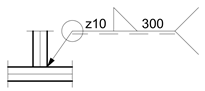
6. Weld size - With the ISO system, the weld size is placed to the left of the weld symbol and is preceded by the letters: (z) / (a) / or (z) - depending on whether the leg length or throat thickness is to be specified. Unless otherwise instructed, it is usually the leg length that is specified, in which case only the (z) box needs to be added. If the throat thickness is to be specified, only the (a) box needs to be entered.