Bracing
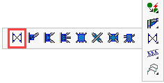
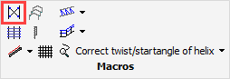
Command - PrB_Bracing
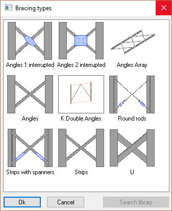
Activating the Bracing command will bring up the following bracing options dialog, from which you are prompted to select the Wind Bracing configuration.
After that, the Fixing the bracing dialog is shown where you are prompted to fix the top and bottom bracing elements:
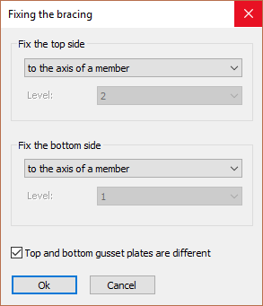
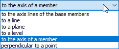
The options for fixing the top and bottom bracing elements include:
All bracing will be drawn on the axes of the main members - which may be either columns or main lateral profiles.
The bracing fixing options only apply to transverse members.
- To the axis lines of the base members - This option will draw the selected bracing between the ends of the 2 main profiles, ignoring any transverse members.
- To a Line - The model line should be drawn to intersect with the axes of the base members.
Note!
- In case the line extends beyond the length of the base member and there is no real intersection, then Parabuild will use the apparent intersection of the line with the main member axis. In this case, the gusset plate connection(s) might be drawn outside of the members in the air.
- In case the line is not drawn in the same plane as the plane of the bracing and thus no real intersection, then Parabuild will project the line to the plane of the bracing to obtain the intersections. - To a plane - The same procedure as with lines, but in this case the intersection of the plane (surface) with the members axis is used.
- To a level - The same procedure as with planes, but the difference is that these planes are always horizontal. This option therefore cannot be used for bracing in the roof. (You will be prompted to enter the applicable levels)
- To the axis of a member - The same procedure as with lines, but in this case the axis of the selected member will be used.
- Perpendicular to a point - You will be prompted to select a point (for example a point of a plate). The start point is then determined by projecting the point perpendicular to the member axis.
Top and bottom gusset plates are different - When you activate this option, Parabuild will show you the gusset plate selection dialog box twice. The first time for the top gusset plates and the second time for the bottom gusset plates
If this option is deactivated, the gusset plate dialog box will be shown just once and all four gusset plates will be the same.
When you click on Ok, the following prompts will show on the command line:
Select the left profile on the side where the bracing should be placed: and Select the right profile:
We select the backside of the flange of the member, on the side of the bracing
Hereafter the Gusset plate connections dialog box appears :
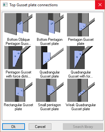
We choose the desired gusset plate and click on Ok.
It is acceptable to click the cancel button at this stage. In this case the bracing will still be drawn but without gusset plates.
Now the dialog box Connections for the middle of the bracing appears:
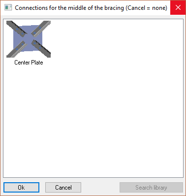
We choose an option and click on Ok.
It is acceptable to click the cancel button at this stage. In this case the bracing will still be drawn but without the center connection.
Now Parabuild draws the wind bracing.
The previous prompts are repeated so that you can draw the same bracing on other locations.
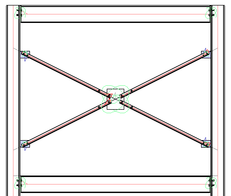
This example shows an angle cross brace with a center plate.
The bracing edit dialog
After completing the bracing, all of the dialog s of the newly drawn parts are displayed.
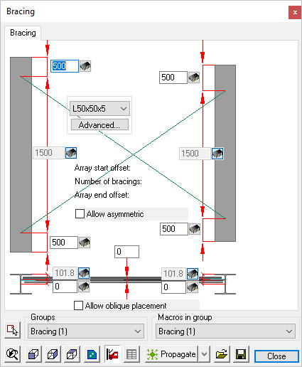 Bracing
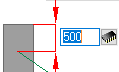 Change the offset at top and at bottom. Only the values to the left apply because Parabuild has drawn a symmetric bracing. If we activate the Allow asymmetric checkbox, the values to the right will apply too.
- Change the member section by using the drop down tool.
- Choose another section type by using the Advanced... button.
Note! if you change the profile type of the bracing using this tool, then the gusset plate connections will likely become corrupted. In this case you should redraw them.
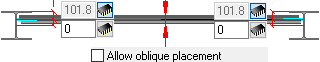
- Change the horizontal position of the wind bracing. This is possible by changing the position of the bracing axis relative to the member axis or the member edge. Only the left values apply.
- If you activate the Allow oblique placement checkbox, then the right values also apply. This last setting gives you the possibility to draw a bracing between members whose axes are not aligned.
- Note! The gusset plates that Parabuild has drawn are suggestions and should be reviewed to make sure the dimension adhere to the load calculations.
The gusset plates can be modified individually with the Review macro command on the 4 smaller spheres.
For more information on these macro dialogs, see the topic Review macro dialog.
Gusset Plates
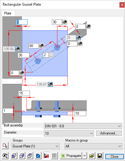 Here you may edit the gusset plates connecting to the main members.
The gusset plates can be modified individually with the Review macro command on the 4 smaller spheres.
For more information on these macro dialogs, see the topic Review macro dialog
Center Plate
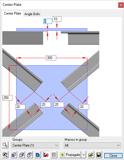 Here you may edit the center plates connecting the bracing members
The center plates can be modified individually with the Review macro command on the specific macro sphere.
For more information on these macro dialogs, see the topic Review macro dialog