Plate
The 'Plate' object type has the following headings:
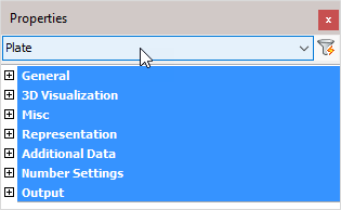
General: Is common to all object types, and covers general AutoCAD and BricsCAD settings, including: Color / Layer / Linetype / Linetype scale / Plot style / Lineweight / Transparency / Hyperlink / Handle /
3D Visualization: Is also common to all object types and includes: Material.
The material that is referred to here is only the visual representation material. For changing the actual material of parts, see the Additional Data section of plates, profiles or structures.
Misc
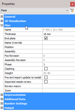
Note! - * indicates that the given value is a resultant of the sum of other values in the panel - and cannot be individually edited.
Name: * This is the plate size, also shown in the BOM. Refer to the Settings dialog box for influencing this name
Thickness: Plate thickness - editing this value will immediately reflect on the model
End Plate: A plate, designated as an 'End plate' will receive an additional view on the assembly drawing
Name Override: The replacement of the normal plate name. This replacement name will be used in all part lists and workshop drawings.
Position: * The number automatically given to elements by Parabuild. Elements that are the same, (same dimensions, holes, sections) are given the same position number. These positions are partially adaptable with prefixes and suffixes.
Assembly: * Assembly number
Pos Revision: * Position revision number
Assembly Revision: * Assembly revision number
Phase: Change the project phase of the selected element
Clashing: This is set to yes or no and refers to whether the profile is currently clashing with other elements or not. This property is automatically set by the clash control, and is primarily included in properties for search objectives. For more information read the chapter Clash Check
Weight: * Calculated weight of the selected member
Prevent import update to model: Activating the checkbox will prevent any import update to the model. This refers to CIS/2 or Ifc incremental imports.
Imported needs review: This value will be set automatically for parts that were updated after an incremental CIS/2 or Ifc import.
Review macro: Will open the macro edit dialog, where the macro may be viewed and/or edited
Zoom: Pressing the button will zoom to the extents of the selected plate
Representation
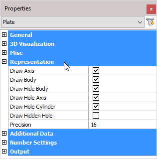
Draw Axis: Draws the Axis of a profile
Draw Body: Draws the complete 3D-model of the profile in 2D wireframe
Draw Hide Body: Draws the complete 3D-model of the profile in 3D visual styles
Draw Hole Axis: Draws the axis of every hole in the plate
Draw Hole Cylinder: Draws the cylindrical path of all holes in the plate in 2D wireframe
Draw Hidden Hole: Draws the cylindrical path of all holes in the plate in 3D visual styles.
One can activate the hole subtraction here for a better visual representation, but do note that when a bolt is drawn through this hole, you would not see the difference. On top of that, the subtraction is heavy on resources. This is the reason why this option is disabled by default.
The edges of the hole are always drawn independently of this setting.
Precision: This value applies to the precision of curves in the plate's internal or external contours.
Additional Data
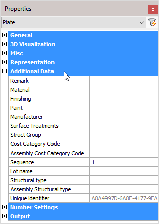
Remark: Can be used in a variety of ways. This field is maintained for every element. It has its own column in the part lists, and can be used for sorting part lists and workshop drawings. This property has no further influence
Material: This field also has its own column in the part lists and can be used for sorting, but this has a direct influence on the position number (and consequently the mark number). Two elements that are identical, but have another material assigned to, will be given another position number. This enables a total categorization of different materials in part lists and workshop drawings.
The weight factor of every material can be changed in the Parabuild Properties > Global > Material/Finishing. Parabuild will use this weight factor to calculate the weight in the part lists.
Finishing: Same as Remark
Paint: Same as Remark
Manufacturer: Same as Remark
Surface Treatments: Will open the Surface Treatments dialog
Struct Group: This property can be freely used for the user's own purpose.
Cost category Code: These codes are usually determined while a quote for the project is made. This code can then later be assigned to the 3D model when the project was ordered. This way the parts can be traced from estimation to production and to completion inside ERP/MIS software. This value is exported to KISS files.
Assembly Cost category Code: See ‘Cost category Code’
Sequence: The erection sequence of the part. This value is exported to KISS files
Lot Name: The lot that the part belongs to. This value is exported to KISS files
Structural Type: ** For example: Bracing/Rafter/Stringer/Handrail/Post/etc....**
Assembly Structural Type: **For example: Stair/Railing/etc....**
Unique Identifier: * Unique identifier allocated by Parabuild, or received from a CIS/2 or Ifc file import.
Number Settings
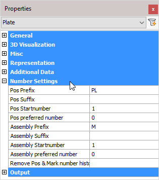
Pos Prefix: Determines the prefix of the position number.
Pos Suffix: Determines the suffix of the position number.
Pos Start number: Determines the start number of the position number.
Pos preferred number: Forces Parabuild to use the preferred number as position number. Parabuild will comply if this number is not already in use by a different part.
Assembly Prefix: Determines the prefix of the Assembly/Mark number.
Assembly Suffix: Determines the prefix of the Assembly/Mark number.
Assembly Start number: Determines the start number of the Assembly/Mark number.
Assembly preferred number: Forces Parabuild to use the preferred number as assembly/mark number. Parabuild will comply if this number is not already in use by a different part.
Remove Pos & Mark number history: Lets Parabuild forget the preferred numbers and also the previous numbers that the part had.
Note! For more information on any of these items, refer to Numbering of elements
Output
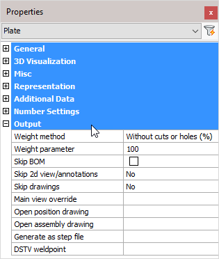
Weight method:
- Without cuts or holes (%): The weight of the complete length of the profile will be calculated, without subtracting the holes and cuts. In the next property you can adjust the percentage of this value that should be used.
- Cut: The cuts in the profiles are subtracted to calculate the weight.
- Cut and drilled: The cuts and the holes are subtracted to calculate the weight
- Fixed value: The value you enter in the next property will be used as the weight for this element in kg or lbs (This value will be taken over in the BOMs without any adjustments).
Weight parameter: This property is being used in combination with the above properties ‘Default’ and ‘Fixed value’
Skip BOM: If this property to ‘Yes’, this element will not appear in the BOMs
Skip 2D view/annotations: Adjust this to skip this element for the 3D annotations or the 3D annotations + 2D view
Skip drawings: You can skip only the Pos drawings, only the mark drawings, or both the Pos and Mark drawings
Main view override: Select a plane that determines the main view's direction
Open position drawing: Will open the position drawing of the selected part
Open assembly drawing: Will open the assembly drawing of the selected assembly
Generate as a STEP file: STEP file is a CAD file format, usually used to share 3D models between users with different CAD systems. Note! This command will only work in BricsCAD and when the Communicator module is installed and licensed. For more information, refer to Settings for Workshop Drawings > Generate STEP Files
DSTV weld point: DSTV weld points are points that are placed in the automatically produced DSTV NC-files. A point indicates on which spot an element must be welded on the profile. For more information, refer to parabuild Settings > Global > DSTV Weld points