Settings for page and layout
In this dialog we can choose the standard drawing sheet templates.
It is possible to personalize the templates to reflect your company's or clients identity.
To do this, you can open and modify these template .DWG files in the Parabuild directory: Parabuild\Pb_Lib\Workshop drawings\
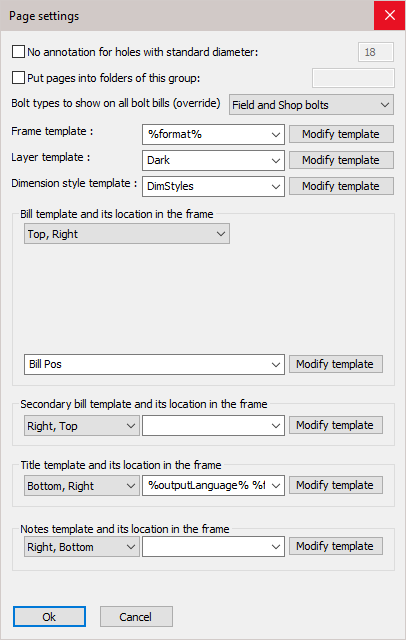
In this dialog box you can change the following settings :
No annotation for holes with standard diameter - Checking the checkbox will result in holes with the given diameter not getting any annotations on the 2D drawings. Not implemented yet
Put pages into folders of this group - Not implemented yet
Bolt types to show on all bolt bills (Override) - With this option you can set the type of bolts that will be fed into all the bolt bills that are activated in the lower settings
Frame template - By default, this is set to %format%. It is important to keep this variable, because the frame template to be used is dependent on the format. As the format is chosen automatically by Parabuild, we can't enter an actual format here but we use the variable to automate the frame template selection.
Layer template - Here you may switch the layer template from light to dark. Both templates were created to accommodate users working with a light background while others prefer to use a dark background for sheets. Do note that the layers are usually only inserted the first time per 3D drawing. After the first time, the layers exist already and they are not overwritten.
Dimension style template - The dimension styles in this template drawing will be inserted in the current 3D drawing, so that the styles can be used for dimensions on the 2D drawing.
Bill template and its location in the frame - This is the main bill that contains the list of all parts on the 2D drawing
Secondary bill template and its location in the frame - The secondary bill is usually used to list all the site and/or shop bolts that are linked to the parts on the 2D drawing.
Title template and its location in the frame - The title blocks of the sheet can be personalized by opening the drawings in the folder : \Parabuild\Pb_Lib\Workshop drawings\Title Templates\
The default value is "%outputLanguage% %format%", which could result in for example "English A4". So in that case the file "English A4.dwg" will be used in the Title templates folder.
Both strings can variate, so therefore the variables are necessary.
If the user works for several contractors that each want their own logo on the title block, then this can be accommodated by using the variable %Contractor_Name%.
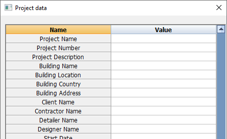
This variable can be entered in the Project data of the 3D drawing.
For this to work, the user will also have to create the title blocks for each contractor.
Notes template and its location in the frame - The notes is an extra template that can be used to freely add more information on the sheet.
More about frame templates
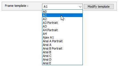
These template files are located in the folder \Parabuild\Pb_Lib\Workshop Drawings\Sheet Templates\.
The overall size of the templates will match with the size of the standardized ISO or ANSI sheets.
Should you wish to create a non-standard template, then you can add a new frame template here, but don't forget to also add the accompanying format in the Format scales dialog.
More about Title Templates
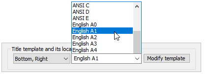
These template files are located in the folder \Parabuild\Pb_Lib\Workshop Drawings\Title Templates\.
You can add or delete text fields, rename the fields, rearrange them, and add your own or the companies identity in the form of a logo.
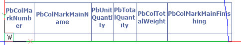
The default template is shown above.
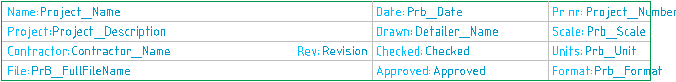
Each row first contains the title header and then the variable - e.g. Name: Name
The variables will be resolved through the Parabuild General / Project data dialog.
By entering the appropriate values adjacent to the Name will substitute the variables in the title block template.
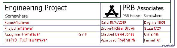
A typical edited title block with fields added, together with the company logo
More about Bill templates
These template files are located in the folder \Parabuild\Pb_Lib\Workshop Drawings\Bill Templates\.
The column titles are normal texts inside a table object. Just double-click a text field to edit them.
You can add or delete columns or rows, rename rows, and rearrange them all with the BricsCAD/AutoCAD table tools.
The column headings are variables and will be replaced with their values in the bill. For a list of available variables go to Settings / Settings for objects on the page / Show all properties