Annotation styles
Command - Prb_TagSettings
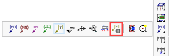
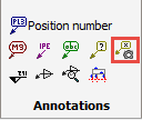
Activating this command will open the Managing annotation styles dialog, which can also be accessed from the Sheet Properties dialog.
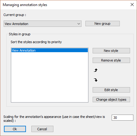
This dialog allows you to create and modify annotation styles. Each annotation style is part of an annotation group.
The purpose of the annotation group is to allow us to access multiple styles from a single icon.
If we take for example the Position number group, which is accessed through this icon  : we can use this icon to draw a part number tag or a bolt tag, both of which have a completely different annotation style.
This is accomplished by adding multiple annotation styles in the group, and also by correctly setting the Object types per style (explained below).
The group name can be used directly on the command line to draw annotations using the command name as follows :
(Prb_TagGroup "Group name")
By using the above line as the command line command in a new icon, it is possible to create custom icons that access custom annotation styles.
Alternatively, we can also access custom group names from the Other Annotations command in Parabuild. Creating a new icon is not necessary thanks to this command.
The actions in this dialog are explored below :
Current group and New group - These allow you to manage the groups
New style - This will create a new style within the current group
Remove style - This will remove the selected style
Edit Style - This will open the Settings for annotations dialog
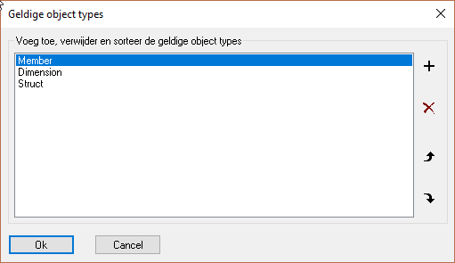
Change object types - This allows us to change the object types for the currently selected style.
As explained above, the object types in this list allow us to dictate which style should be used for each different object type.
Settings for property annotations
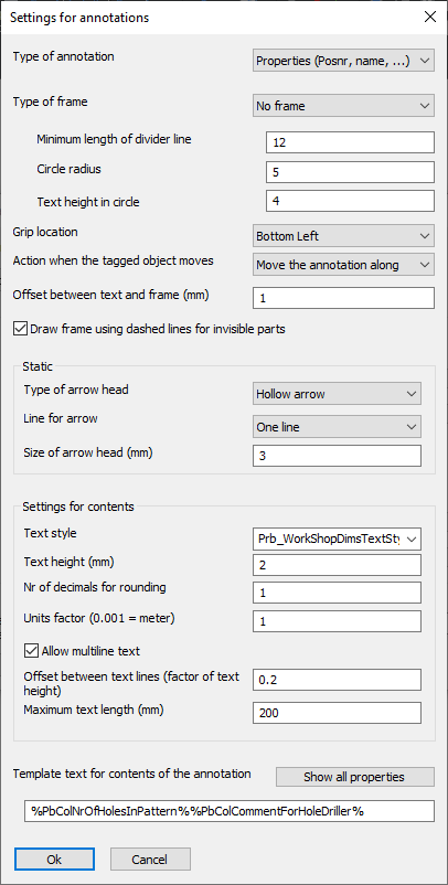
Many of the options in this dialog box are self-explanatory, but we will explore the less obvious options :
Type of annotation - The following annotation styles are available :
- Properties - This is the typical annotation that displays one or more properties of a 3D part
- Comment - This annotation type's purpose is to show a manually written comment. In essence there is no difference with the properties type.
- Property through proxy object - This annotation type is the same as the Properties type. But a difference was created here to allow the user to differentiate between an annotation that shows the property of a part directly, or 'by proxy' when the annotation is touching the part indirectly.
An example could be an annotation touching a dimension. Usually, the annotation would not depict properties of the dimension but rather properties of the part that is dimensionned. - Arrow for section view - This type has some unique properties that only apply to section annotations. A section annotation is used to depict the viewing direction and location of a section view. For more about the options, see below.
- Level annotation - This type has some unique properties that only apply to level annotations. For more about these options, see below.
Type of frame - All of the frame types should be obvious except for Text above and below a divider line.
This frame is an annotation with 2 or 3 text fields. For more information about this, see the Minimum length of divider line and Circle radius options.
Minimum length of divider line - This option will only work if the text %HorDivider% is used in the Template text (see below). The purpose of this is to draw an annotation with a horizontal divider that has text above and below the divider line. The contents before the %HorDivider% will be displayed above the divider line, the text after the %HorDivider% will be drawn below the divider line
Circle radius - This option will only work if the text %BubbleText% is used in the Template text (see below). The text that is written after the %BubbleText% will be drawn inside a circle. The circle will be drawn on the left-hand side of the divider line.
Text height in circle - This is the height of the text inside the special %BubbleText% circle.
Grip location - This is the location where the cursor attaches to the frame when we try to move an annotation frame.
Action when the tagged object moves - What Parabuild should do when the tagged part moves. Not implemented yet.
Draw frame using dashed lines for invisible parts - Not implemented yet.
Line for arrow - At the time of writing, only the options None and One flexible line and a fixed line are supported.
Allow multi-line text - When enabled, the text will be shown on multiple lines if necessary. The below options will decide when new lines are introduced :
Offset between text lines - This is measured as a factor of the text height
Maximum text length - If the text field would become larger than this value, then a new line will be introduced.
Template text for contents of annotation - This is the most important option for the annotations.
With this option we can decide the contents that should be written in the annotation.
We need to use variable names to set the properties that should be depicted in the annotation.
But it is still allowed to write regular 'static' text in the same string.
The variables are always entered between % symbols to make this possible.
Some examples annotation texts that demonstrates this mix :
The template text for a hole annotation :
ø%PbColBoltDiamater%
Could result in the text :
ø16
The template text for a profile annotation :
%PbColPosNumber%-%PbColName% L%PbColLength%
Could result in the text :
PR1-IPE200 L3590
Use the button Show all properties to display all the variables that Parabuild supports.
Settings for section annotations
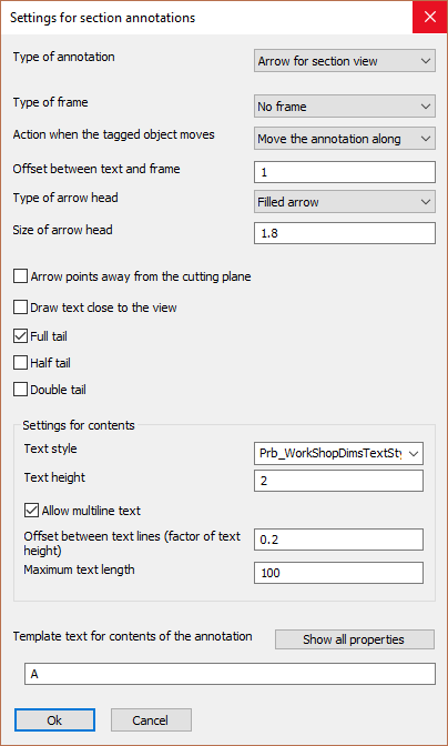
Many of the options in this dialog box are the same as the regular annotations dialog box, except these:
Arrow points away from the cutting plane - Not implemented yet.
Draw text close to the view - Not implemented yet.
Full tail : 
Half tail : 
Double tail - Not implemented yet.
Settings for level annotations
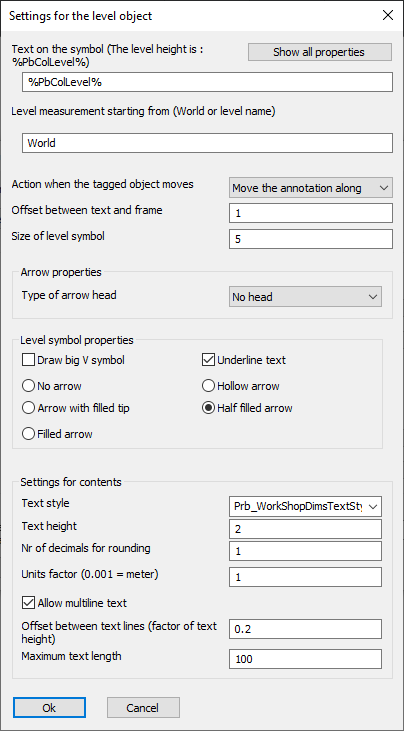
Many of the options in this dialog box are the same as the regular annotations dialog box, except these:
Text on the symbol - This works the same as the Template text of the property annotations. The only difference is that for this annotation type the variable %PbColLevel% can be used.
Level measurement starting from - This should be "World", or the name of the level that should be used as starting plane for the height measurement. Levels can be reviewed in the Modify levels topic.
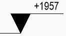
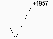
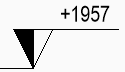
Draw big V symbol :
|
|
An example level annotation with Draw big V symbol enabled |
An example level annotation with Draw big V symbol disabled |
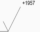
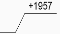
Underline Text :
|
|
An example level annotation with Underline text enabled |
An example level annotation with Underline text disabled |
Tip type or arrow type :
|
|
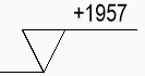
Tip set to : None |
Tip set to : Hollow |
|
|
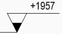
Tip set to : Filled tip |
Tip set to : Half filled |
|
|
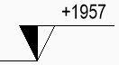
Tip set to : Fully filled |