Applying Connections
The connections from the library are sub-divided in groups, so that selecting the correct connection from the extensive library is made simpler and more intuitive. There are also a geometric filter that reduce the number of connections to choose from.

Some examples of groups are Haunch connections, Apex connections, End plates, Base plates, etc…
Each group has its own icon. After you click on the icon you will be asked to select the base profiles. A logical and intentional consequence determines that all connections of the same group must have the same amount of base profiles.
The order in which you select the profiles is important!
Follow the command line prompts, when selecting the profiles. Generally, you will be prompted to select the supporting member first, followed by the connecting member. In cases where this is not clear, we can follow the rule of first selecting the profile that should not be modified in length, and afterwards the profile that will be lengthened.
If you select in the wrong order, the orientation of the resulting connection will be wrong.
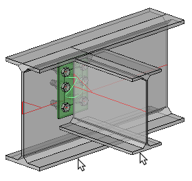
Its possible to inadvertently mirror connections by not being consistent when selecting the sections using the mouse pointer. To avoid surprises you should always select the underside of the members, thus ensuring the connection will be drawn correct.
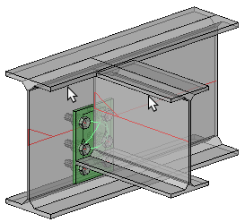
Selecting the tops of members may mirror the connection (upside-down) as illustrated in the example below.
|
|
Result after selecting the underside of the members |
Result after selecting the tops of the members |
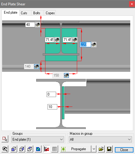
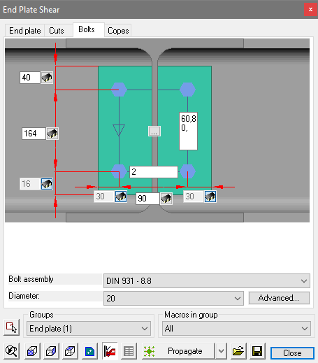
This 'mirroring' can be a nuisance because its not evident when editing the connection macro dialog - the edited dialog (Below) is identical for both the options shown above - but you can clearly see the difference with the end result - these differences are based solely on the manner in which the members were selected.
|
|
The edited End Plate tab |
The edited Bolts tab |
Geometric Filters
The base profiles selected are checked against those in the library to determine which connections are applicable. This is a filter that happens automatically.
The connections that are not compatible with the chosen profiles will not be visible.
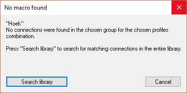
For example: a typical haunch connection would imply that the beam connects to the column flange, should the orientation be such that the beam is connecting to the column web, Parabuild will check the library, and if no suitable connection is available the following window will be displayed offering Parabuild to check the entire library for a suitable alternative.
Inserting a macro from the library
After you have chosen a connection and clicked on Ok the connection is inserted and a dialog box will be opened that allows you to adapt the dimensions of the connection. (The chapter Macro Edit Dialog box discusses this dialog box)
Deleting unwanted parts of a connection
You are free to remove a part of the connection (components such as plates or profiles). The macro will not redraw the elements that you have removed. All other elements of the macro will usually continue to work normally after this, depending on the situation:
For example you can remove the stiffeners of an apex connection without any impact for the other parts of the connection.
The only parts that we should avoid removing is the base profiles themselves. Once 1 or more base profiles have been removed, Parabuild does not have enough information to calculate the location of the objects in the connection.
As a consequence, the macro sphere may become red and the objects in the macro might move to unwanted locations.
In this case it is advised to erase the macro.
Deleting bolts in a macro
We can delete bolts that were drawn by a macro bolt pattern.
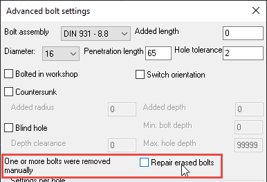
When a bolt has been manually deleted, Parabuild will not try to restore the erased bolt.
If you do want to restore the deleted bolt(s), then use the checkbox in the Advanced bolt dialog box :
Deleting the macro sphere
You are free to remove just the macro sphere. The components of that macro will stay intact, but they will no longer be automatically adapted because the macro sphere takes care of that.
Also the part sizes can no longer be adapted. The connections elements become "Static parts" as if they were drawn manually.