Camera
The camera is used as the driver for views.
It is always located in the 3D model, and determines :
- The viewing direction in 3D
- View clippings
- Additional filters on 3D model selection
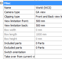
The camera has the following properties :
Name - The name of the camera, as it will be shown in the Sheets Manager
Camera type - This relates more to the type of sheet on which the view is located (plate, member, assembly or GA)
Clipping type - Clipping is used to filter out unwanted 3D models from the view, as they would obstruct the view on the subject models that we want to show on the view.
|
|
A camera with Front/Back limitation |
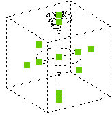
A camera with Box limitation |
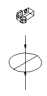
View limitation front/back - This will only work the Front/Back clipping type is enabled.
Front limitation is measured from the circle of the camera (see illustration) to the camera symbol. Back limitation is measured from the circle to the opposite side.
Box Width/Length/Height - This will only work the Box clipping type is enabled.
The grip points can be used to stretch the box. The grip points are shown when you select the camera in 3D (they are shown as green squares in the illustration).
Included parts - With this button you can force the view and camera to only show a certain selection set of 3D models on the view.
Excluded parts - With this button you can force the view and camera to never show a certain selection set of 3D models on the view.
Switch orientation - This button will switch the orientation of the camera in 3D.
Take over from current view - This button will rotate the camera as such that it matches the current 3D view you are currently using.
Note!
After applying a change to any of the properties in the camera, you will need to refresh the view in order to see the changes on the view.
You can refresh views with any of these 3 methods :
- The function key <F5> will refresh the visible views on a sheet
- The view has a refresh property button
- You can right-click on a sheet in the sheets manager to refresh all the views on the sheet