Draw Framing
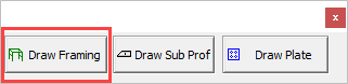
With the Draw Framing action button you can draw columns, beams and rafters. Additionally, you can also draw side rails, purlins, joists and all longer profiles of your structure.
The profiles that you draw are based on :
- Grid lines
- Levels
- Other profiles that already exist in the drawing
- The World coordinate system (in case there are no grid lines)
Drawing profiles will become easier when using the functions offered by the Context Buttons
Before drawing the skeletal frame, it is recommended but not obliged to first:
This is so that you may take advantage of the View manager functions and importantly, when planning and preparing 2D views in the General Arrangement drawings.
An additional advantage will be the relations between the members, the grids and the levels. The context modeler will create the relations between them automatically and later when you modify the grid or a level, the profiles will follow suit.
Drawing Columns
 Ensuring that the levels are set as required, select a profile from the Selection options and press Draw framing - the column will be attached to the mouse pointer which may be placed anywhere on the model relative to the grid lines. When placing the column on a grid line, its orientation may be changed by moving the mouse pointer along either the X or Y axis - when satisfied with the orientation, press the left mouse button to accept. You may continue adding columns - but the selected orientation will remain. Terminate the operation by either clicking the right mouse button, or pressing <Enter>
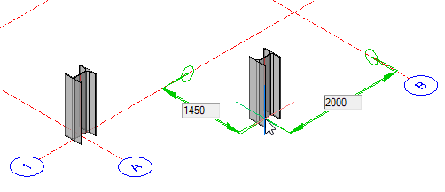
When placing columns off grid lines, Parabuild will automatically recognize the closest grid intersection, and any offsets will be indicated by editable dimension boxes.
If there are no grid lines, the column will be placed relative to the WCS
Once the column has been placed it is effectively constrained to the placement point and cannot be moved with the AutoCAD/BricsCAD move command. To move or modify that point, it's necessary to edit the constraints.
Alternatively, one can use the Advanced property of the profile to disconnect the profile from it's macro, so that manually moving the profile becomes possible.
Modifying Constraints
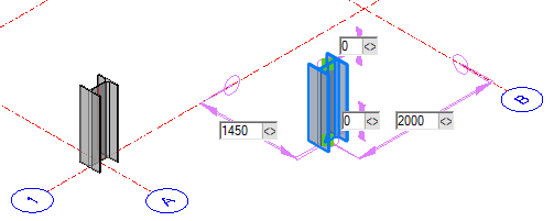 Clicking on the column will reveal the editable constraints - the relative points include dimensions on the X, Y, and Z axes. Here you may enter different values which will immediately be reflected on the model.
Alternatively, you may edit the constraints by using the drag constraint function 
Activating this function you will be prompted to: Move the mouse to modify the constraint, then left-click to accept:
Once complete, click the right mouse button or press <Enter>
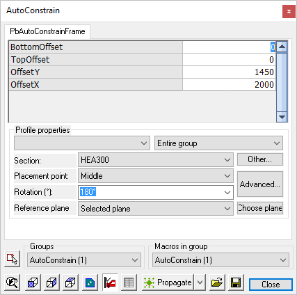
Double-clicking the column will open the AutoConstrain dialog. Here you are presented with more options for editing the constraints, which include the offsets listed above, but in tabular form, and additionally:
- Section - Where you may choose another profile from the group by selecting from the drop-down menu
- Other - Will open the Select profile dialog where you may select a different group and profile
- Placement point - Where you may select a new placement point from the drop-down menu - alternatively you may select Advanced.
- Advanced - Which will open the Profile Placement dialog
- Rotation - Where you may change the profile rotation
- Reference plane - Where you may select the reference plane
- Choose plane - Where you are prompted to select a reference plane to match the section rotation to another part