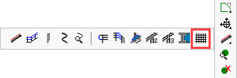
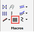
Draw Grating
Command - PrB_Grating
This command allows you to draw floor grating or raised pattern floor plates over a defined surface area. The flooring options include:
PLBG - Press lock bar grating
WBG - Welded bar grating
SLBG - Swage lock bar grating
RPFP - Raised pattern floor plates
These options are explained in more detail under Floors
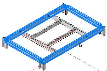
You will be prompted to select the entities that define the boundary for the floor, when don, press <Enter> The floor will be automatically drawn accompanied by the edit dialog.
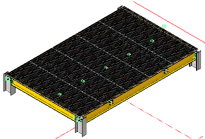
The floor panels will be placed as an array at the extremities of the selected entities with the bearing bars running in the direction of the shortest span. The floor panels are set according to the selected standard width. These widths have been established by Parabuild at 800 mm, 900 mm, 1000 mm, 1100 mm, and 1200 mm.
At the time of writing, the command only supports flooring patterns of which the contour is described by 4 profiles.
Note! Standard widths, maximum panel lengths, bearing bars, transversal bars, may be customized to suit regional or manufacturers standards by editing the Flooring Profile Library. The same library allows you to create new libraries to meet the above criteria.
The floor panels will be placed, with the width of the last panel being non-standard to accord with the total overall width of the defined surface area. This may be edited in the flooring edit dialog.
|
|
Select Entities |
Draw Grating |
The initial flooring edit dialog will edit the entire flooring array providing the following options: Individual floor panels may be edited by using the Review macro command.
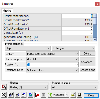
OffsetFromExterior2 - (Variable) - The offset between the floor panel and the right side extreme edge of the defined surface area
OffseFromInterior2 - (Fixed) - The value given is representative of the width of the top flange of the beam. This value will update as the former is edited.
OffsetFromExterior2 - (Variable) - The offset between the floor panel and the right side extreme left of the defined surface area
OffsetFromInterior2 - (Fixed) - The value given is representative of the width of the top flange of the beam. This value will update as the former is edited.
VerticalGap - Is the distance between the top of the floor beams and the underside of the flooring panels
GetWidthLoadBearing1 - Is the flange width of the top load bearing member
GetWidthLoadBearing2 - Is the flange width of the bottom load bearing member
OffsetFromLoadBearingExterior1 - (Variable) - The offset between the floor panel and the top side extreme edge of the defined surface area
OffsetFromLoadBearingInterior1 - (Fixed) - The value given is representative of the width of the top flange of the beam. This value will update as the former is edited.
OffsetFromLoadBearingExterior2 - (Variable) - The offset between the floor panel and the top side extreme edge of the defined surface area
OffsetFromLoadBearingInterior2 - (Fixed) - The value given is representative of the width of the bottom flange of the beam. This value will update as the former is edited.
GapBetweenGratings - Is the gap between the grating panels
TotalLength - This is the total length of the area from first to last beam.
Start and End offset (Grating array) - This will set the start and end offset of the entire grating array measured from the defined surface area
Distance between entries (Grating array) - This value is derived from the floor panel width and the gap between panels. This value will automatically update as the gap between panels is changed.
Number of entries (Grating array) - The number of panels forming the flooring array
Profile Properties
From the drop-down menu - Strip - All the grating panels are grouped under the name Strip. In other macros, more or other group names might be listed here.
From the drop-down menu - Entire group - Select this to edit all of the grating panels
Section - From the drop down menu you may select a different flooring type e.g. panel width, depth, bearing bar .....
Pressing the Other button will open the Select profile dialog, where you may select flooring from another group (PLBG, WBG, SLBG, RPFP)
Placement point - From the drop-down menu, you may select the placement points for the individual floor panels in the array. pressing the Advanced button will open the Profile placement dialog - where you may edit all the profile properties and placement.
Rotation - where you may select a vertical rotation angle from the drop-down options menu.
Reference plane - where you may select from the drop-down options menu the reference plane options, here you have the option to select a plane by pressing the Choose plane button. By default Parabuild will place the floor panels on top of the selected defined surface.