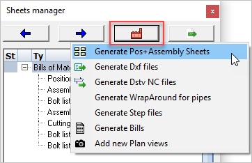
Generate Pos. and Assembly Sheets
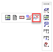
From within the sheets manager, click on  to start the function Generate Pos+Assembly drawings
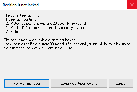
A dialog will appear to warn you that the revision is not locked - here you have the option to lock the revision using the Revision manager or to continue without locking. It is safe to continue without locking.
Before generation of the 2D sheets you will be prompted to select which 3D objects are to be processed.
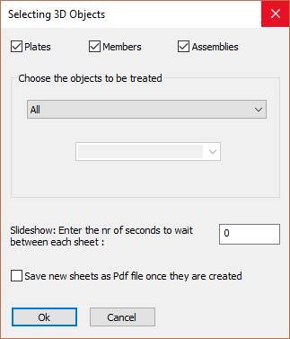
By opening the All drop-down menu, you have the choice to process a part of the 3D drawing, for example a particular phase or revision.
The phase or revision choice you make here will be permanently stored with the 2D sheet.
The number of parts that will be shown on the sheet is only the number of parts counted in the phase/revision selection.
If you've changed the 3D drawing which would cause the number of parts on the sheet to change, then you can start the function Refresh views on the sheet(s) to update the bill on the sheet(s).
The refresh view function is done automatically on all sheets when you print or export the 2D sheets.
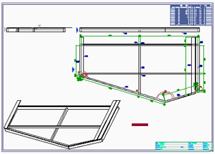
Assembly shown upside-down
Sometimes, the assembly will be drawn upside-down if you use Parabuild's default shop drawing options.
The cause of this is the main profile's Y axis, which is flat (in combination with the No cardinal view direction in the default option)
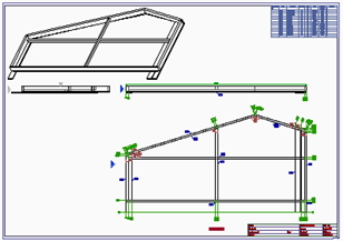
To fix this, we can use the view override of the main part in Properties
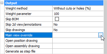
Select the part and open the Properties panel - scroll down to Output and click on the button under Main view override.
Following the command line prompt, Select a plane that determines the main view's direction, or <ESC> to clear the current plane selection
Select the front face of one of the members making up the assembly.
Then it's necessary to Erase Position or Assembly history of the assembly. Otherwise, the existing history will be used which doesn't have the override.
|
|
Before |
After |