CNC contour and matchline settings
Match lines and contours
Match lines and contours can be modified from the Global settings tab : 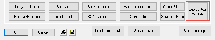
Match lines allow you to scribe short lines or punch marks on the main parts as well as the sub parts, causing them to match.
The hole axis is projected, and here both the main member and the sub-part can be marked with a short line or a punch mark. Those matching lines/marks can then be simply matched up in the shop to position the parts on the assembly.
The sub part that should be welded has a short line on it's side, and the part to which it needs to be welded also has a short line.
These 2 short lines will match up so that the part can be positioned by the welder without any many measuring involved.
At most the welder will need a square to make the lines (or dots) match.
When the to be welded part has holes, the holes are projected and used for the match lines.
The part number of the part that needs to be welded can be added close to the match lines, but this is optional.
The match lines can be replaced for single punch marks that are done with the drill. This is useful in case the machine can't scribe, or the scribing takes too much time.
The match lines can still be combined with the classic contour scribing.
These capabilities will offer the draftsperson and the workshop the following advantages :
- These advanced scribing options replace the manual scratching/marking when laying out the steel, saving significant man hours in the shop.
- Contours, punch marks and hole matching lines are generated directly from the 3D model and can reduce mistakes on the shop floor.
- The capability to use punch marks on some types of parts coupled with scribing on other types can save time on the beamline by using punch marks there, while still having the option to use full or corner contours and scribed hole matching lines on plates.
- Scribing contour and/or part numbers can be skipped entirely for specified situations. This offers further opportunities for optimizing the utilization of the machines in the shop.
- Automatic scribing options can be configured based on the type of part. These settings only need to be configured once, and after that CNC files for the whole model can be generated automatically. This will save the draftsperson time in not having to do changes manually.
All together these features will increase productivity of the drafters, shop floor staff, and machines in the shop.
Here are some examples of what is possible with contours and match lines in different situations.
|
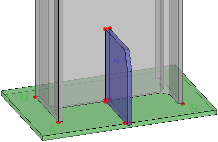
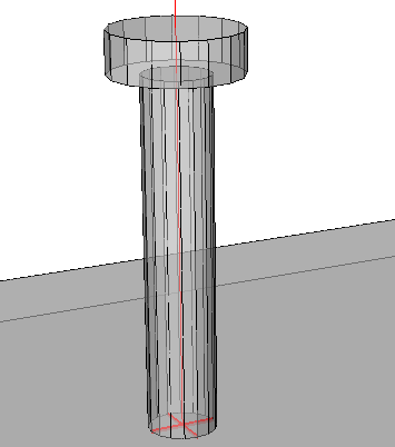
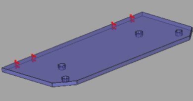
An example baseplate and gusset plate where only match lines were enabled |
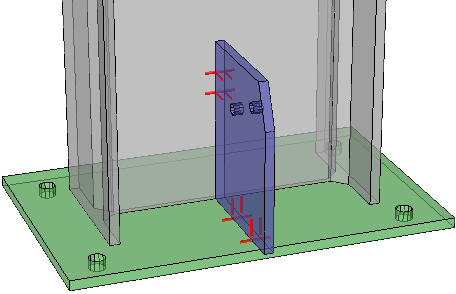
|
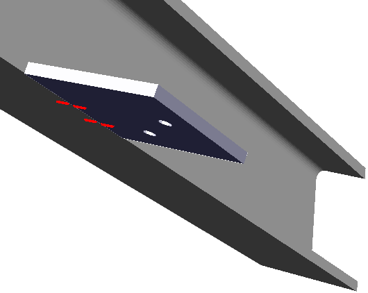
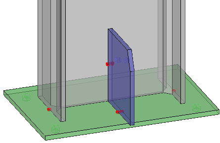
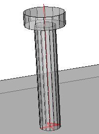
An example with match lines on the plates, and punch marks on the profiles |
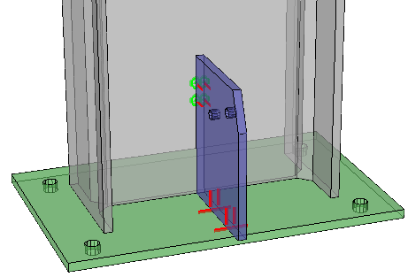
|
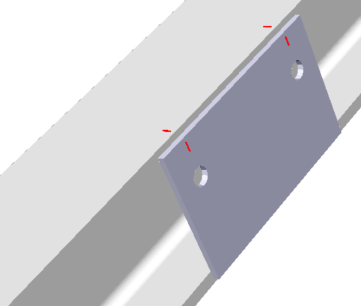
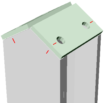
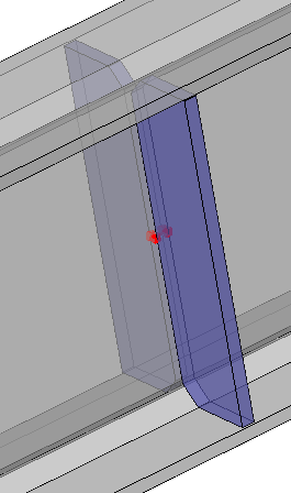
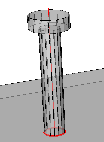
An example of brackets where match lines are transferred to the top flange automatically. There are also sub parts that have contours for other sub parts, this is optional and can be turned off. |
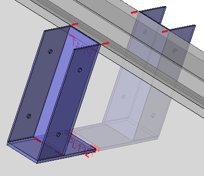
|
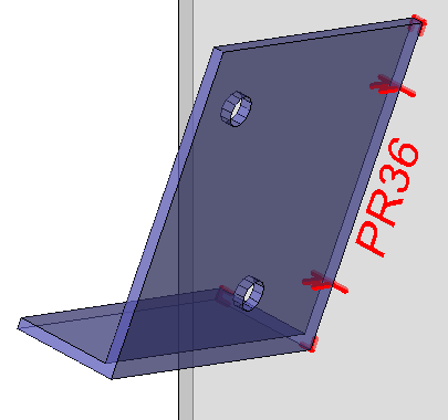
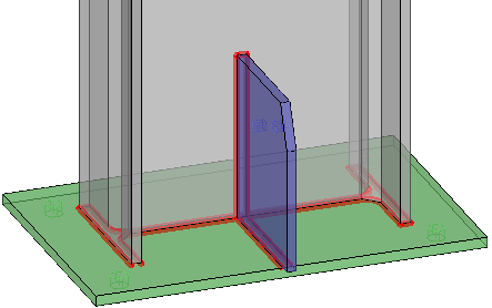
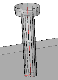
An example of corner contours combined with hole match lines |
|
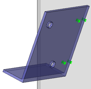
The same example as above, but with punch marks on both the main part and on the attached part, no contours and no part numbers |
|
Another example of corner contours combined with hole match lines |

|
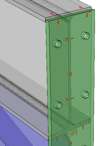
Hole match lines were transferred to the flange automatically |
|
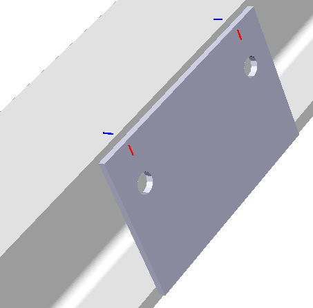
Example of a haunch connection end-plate, with it's hole match lines transferred to the flange. The scribing on the outside of the end-plate can be turned off |
|
Example of a toe plate where the hole match lines were transferred to the flange |
|
Example of double end plates where hole match lines are transferred to the flange |
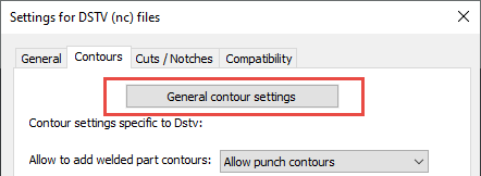
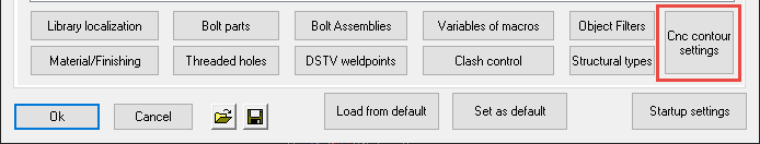
To configure the match lines and contours, use this button from within the DSTV NC Settings dialog :
Or, from the Parabuild Global settings dialog box :
We will explore all of the options in the contours dialog :
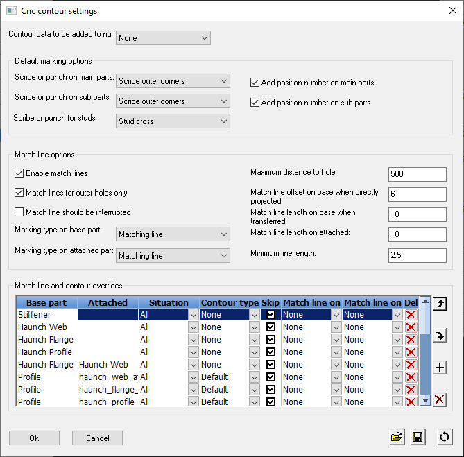
Contour data to be added to numbering - This is the same option that can also be changed in the Parabuild general settings.
This option is explained in detail in the Check contours when numbering parts topic.
Default marking options
Scribe or punch on main parts - This option allows to add a marking for the position of parts that need to be welded.
You can change here what type of markings should be added on main parts.
This setting has the following options :
Each option is illustrated with an example of the results. These are graphical representations drawn by Parabuild on the 3D model, for verification of the chosen Dstv options. We can have a better preview of the scribing and punching results without having to open the dxf or dstv files individually. You can enable this option in the DSTV NC Settings.
- None - This disables the option
- Punch mark at corners - A single punch mark will be added on all the corners of the contour
- Punch mark at outer corners - A single punch mark will be added on only the outer corners of the contour
- Punch mark at outer extent corners - A single punch mark will be added on only the outer extent corners of the contour. So the maximum amount of punches will be 4 per contour
- Punch mark at plate edge in the middle - Instead of the corners, the edges of the plates will each get 1 punch mark, in the middle of the edge
- Scribe contour - Scribes the entire contour
- Scribe corners - Scribes each corner of the contour

- Scribe outer corners - Scribes only the outer corners of the contour
- Scribe outer extent corners - Scribes only the outer extent corners of the contour. So the maximum amount of corners will be 4 per contour
- Scribe outer curves - This will scribe all the outer edges, so inner edges will be skipped
- Scribe a line in the middle of the plate edges - The edges of the plates will each get 1 short line scribed, in the middle of the edge
Scribe or punch on sub parts - This option allows to add a marking for the position of parts that need to be welded.
You can change here what type of markings should be added on sub parts.
See above for an explanation of the available options
Scribe or punch on studs - This option allows to add a marking for the position of parts that need to be welded.
You can change here what type of markings should be added for studs.
This setting has the following options :
- None - This disables the option
- Stud center punch - A single punch mark in the middle of the stud's position
- Stud cross - Will scribe a cross that is comprised of 2 lines
- Stud linked cross - Will scribe a cross that is comprised of only 1 line
- Stud circle - Scribes a single circle in the middle of the stud's position
- Stud center corner - Scribes a corner in the middle of the stud's position
- Stud bottom left corner - Scribes a corner in the bottom left corner of the stud's position
Add position number on main parts - When enabled, the punch marks or scribings on the main parts will be accompanied by a text of the part's position number that should be welded there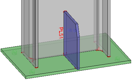
Add position number on sub parts - When enabled, the punch marks or scribings on the sub parts will be accompanied by a text of the part's position number that should be welded there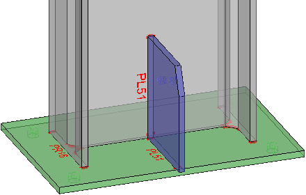
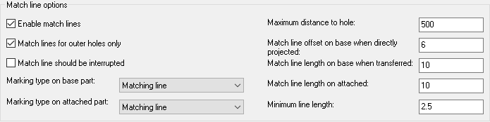
Match line options
Match lines allows you to scribe short lines or punch marks on the main parts as well as the sub parts, causing them to match.
With only minimal scribing or punching, parts can be positioned accurately with just a square, at the position of the holes.
These match lines can be used in combination with contours or separately.
Enable match lines - Enables or disables this feature
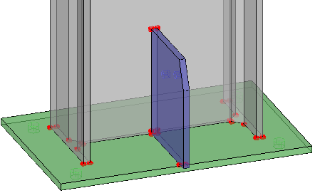
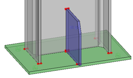
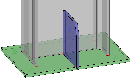
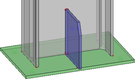
Match lines for outer holes only - When a part has more than 2 holes, only the 2 outer holes will get match lines
|
|
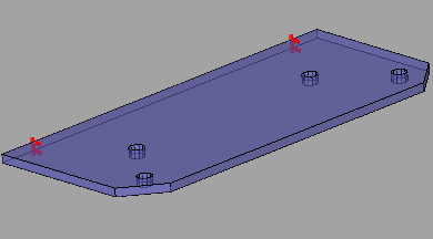
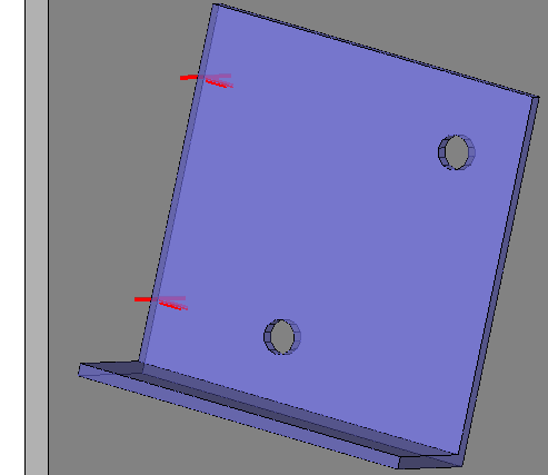
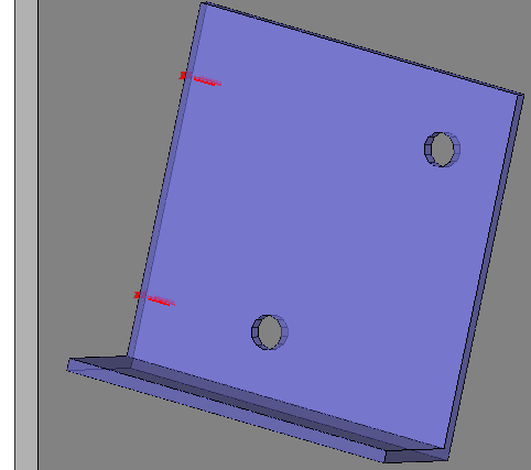
Example with Outer holes only disabled |
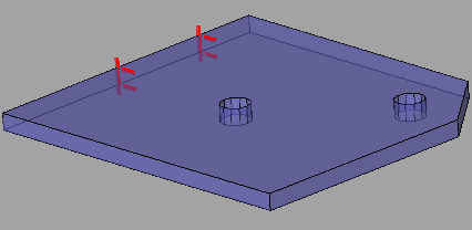
Example with Outer holes only enabled |
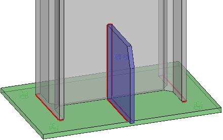
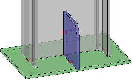
Match lines should be interrupted - Match lines that are destined for the same hole can be optionally interrupted where the part intersects the match line.
|
|
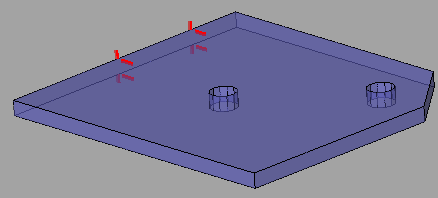
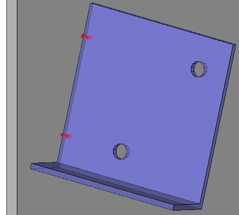
Example with Interrupted disabled |
Example with Interrupted enabled |
Marking type on base part - Specifies what type of marking should be done on the base parts
This setting has the following options :
- None - Disables the marking on base parts
- Matching line - A line will be added that will match up with another line or punch mark
- Matching punch mark - A punch mark will be added that will match up with another line or punch mark
Marking type on attached part - Specifies what type of marking should be done on the attached parts (the part with the holes)
See above for an explanation of the available options
|
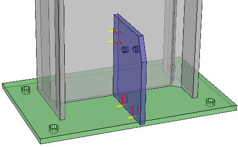
An example with the match lines enabled on the base part and the sub part |
|
An example with the match punch marks enabled on the base part and the sub part |
|
An example with the match punch mark enabled on the base part, |
Maximum distance to hole - The maximum distance of the hole to the edge where the objects meet. Holes farther than this will not get match lines or punch marks
Match line offset on base when directly projected - If this is a direct projection of the hole line; how far should the line extend on each side?
The actual line length will be : plate thickness + (offset x 2)
|
In this example, the directly projected match lines on base are shown in yellow |
Match line length on base when transferred - How long should lines be when they were not directly projected, but transferred to another surface.
|
In this example, the transferred match lines on the base are shown in blue |
Match line length on attached - How long should the lines on the part with the hole be. See above for 2 examples of this line type.
Minimum line length - Skip the line if it goes under this length (When part of the line can't be scribed and it was shortened)
Match line overrides
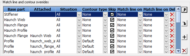
Filters and structural parts can be used to configure which situations should get certain types of scribing. This allows for great user control in the fully automatic scribing system.
For example : Stiffeners are usually generic parts. Even for stiffeners that have parts welded to them it could be beneficial to disable contours, as they could be located with markings on the main instead.
Another example: when scribing position numbers on the material it could be useful to skip the scribing of the position number if it will already be scribed on another part. One such occurrence is when a gusset plate is also welded to an endplate: the position number of the gusset on the endplate is usually plenty and can be skipped on the main.
In this list, each row is an override of the match line and/or contour settings.
The order of the rows in this list does matter : The items will be looped from top to bottom, and the first row that matches the filter ans the situation type will be used.
We will explore all the columns and their meaning :
Base part filter - The criteria to which the base part needs to comply to determine when the override will be activated
Filter names or a structural type can be used. Structural types are checked only if no filter by that name was found.
Attached part filter - The criteria to which the attached part needs to comply to determine when the override will be activated
Filter names or a structural type can be used. Structural types are checked only if no filter by that name was found.
Situation type - Specifies the type of matching line situation this override applies to. The setting has the following options :
- All - The override applies to all contours and matchlines
- Contour - The override applies only to the contour
- Stud - The override applies only to studs
- Matchline - The override applies only to the matchline
- End plate inside - The override applies only to end plates on the inside (the welded side)
- End plate outside - The override applies only to end plates on the outside (the side that is not welded)
- Toe plate holes - The override applies only to the holes of toe plates
- Toe plate extent - The override applies only to the extents of toe plates
Contour type - Enter a contour type that should be used when this override is activated
This setting has the following options :
- None - Disables the contour when this override is activated
- Default - Refer to the general default - this override does no contour override when it is activated
- Undefined - Undefined means that this override says nothing about that contour type so that Parabuild knows to keep going down the list to find it
- All the other options are explained above in the standard matching settings
Skip label? - When this checkbox is active, the match lines or contours will not be accompanied by the position number of the part that needs to be welded
Match line on base part - What type of marking should be used on the base part?
This setting has the following options :
- None - Disables the matching line when this override is activated
- Default - Refer to the general default - this override does no matching line override when it is activated
- Undefined - Undefined means that this override says nothing about that match line type so that Parabuild knows to keep going down the list to find it
- Matching line - Adds a matching line to the base part when this override is activated
- Matching punch mark - Adds a matching punch mark to the base part when this override is activated
Match line on attached part - What type of marking should be used on the attached part? (the part with the hole)
The available options for this settings are explained above in the Match line on base part settings
TIP - If the override only applies to the base part OR the attached part, then set the other to either Default or Undefined.
The last row in the list allows us to add more entries to the list.