Configure View Directions
This dialog box determines the viewing direction and the placement rotation of the view on the sheet.
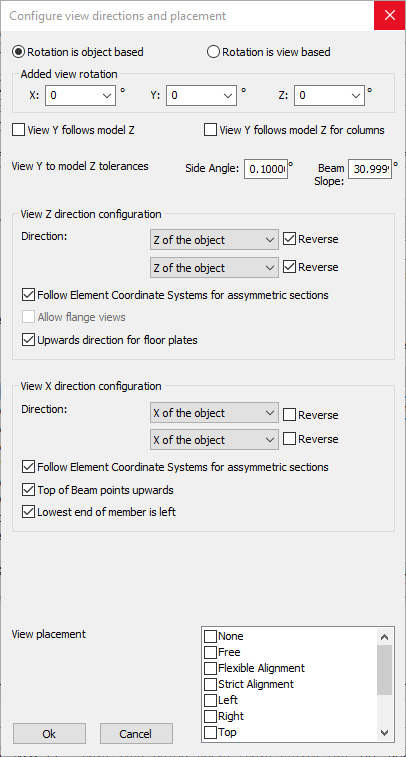
In this dialog box you can change the following options :
View Y follows model Z - When activated, columns will be drawn upright, beams horizontal, rafters sloped, etc...
Each part will have the same slope in 2D as it does in 3D.
This has no influence on columns.
View Y follows model Z for columns - Same as the above option, but this option applies to columns only.
View Z direction configuration
- View Z direction - The Z direction is the viewing direction.
With this option you can choose the viewing direction to follow :
- The object itself, so that we're looking at the part locally (this is the default)
- The world directions, so that we can look at it from the 3D model's direction
- The cardinal directions. The AutoCAD/BricsCAD variable NORTHDIRECTION will be used to determine the cardinal directions in 3D. The front view will then point to the North/South/East/West direction in the 3D model. - Follow Element Coordinate Systems for asymmetric sections - This is an override of the above View Z direction option.
When enabled, it forces Parabuild to use the X Y and Z directions of the object if the object has an asymmetric section shape such as a channel or an angle. This will ensure the for example that the "back plate" of a channel is always drawn visible or always drawn invisible, and not mixed visible/invisible. - Upwards direction for floor plates - This is an override of the above View Z direction option.
When enabled, all floor plates will always point upwards no matter what the other direction options are set to in this dialog.
View X direction configuration
- View X direction - This is the same as View Z direction, but this relates to the X direction of the view instead of the viewing direction.
- Follow Element Coordinate Systems for asymmetric sections - This is an override of the above View X direction option.
When enabled, it forces Parabuild to use the X Y and Z directions of the object if the object has an asymmetric section shape such as a channel or an angle. This will ensure the for example that the "back plate" of a channel is always drawn visible or always drawn invisible, and not mixed visible/invisible. - Top of Beam points upwards - This is an override of the above View X direction option.
When enabled, all of the 'Top of Steel' faces of beams in 3D will always be drawn upward on the view no matter what the other direction options are set to in this dialog. - Lowest end of member is left - This is an override of the above View X direction option.
When enabled, all of the members that have a slope such as rafters and bracings will always be drawn with their "lowest" end in 3D on the left hand side on the view. No matter what the other direction options are set to in this dialog.
View placement - With this option you can influence how free Parabuild can move the view around on the sheet.
The Strict Alignment option refers to the First/Third Angle projection rules : When enabled, the location of the side views and Left/Right views will be strictly done according to the First/Third Angle projections.
The Flexible Alignment does also follow the First/Third Angle projection rules at first, but the views will be displaced when the view alignment takes up a lot of space on the sheet. This can happen for railings, trusses and skids.
Depending on the type of view, Parabuild does not always adhere to all of the options that are enabled here.