Version 8.0 - Migration guide for users
AutoCAD properties changes
In this update several new properties for Parabuild objects have been added.
To make sure that they work well on your installation, it is advised to start Parabuild as administrator the first time after installing this update.
|
Parabuild can be run as Administrator by right-clicking on the Parabuild shortcut |
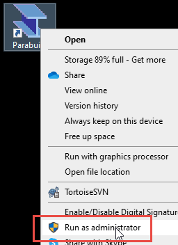
This will register the new Parabuild properties into the AutoCAD installation.
For BricsCAD this is not required because it has a different properties system.
Compatible with BricsCAD V24
This version of Parabuild is now compatible with BricsCAD V24.
Use the Parabuild Startup settings tool to switch between CAD platforms. This tool can be found in the start menu of Windows.
The new workshop and GA settings
Migrating output drawing settings to version 8
Workshop settings have changed so much in this release that it has become impossible to import the old workshop settings from version 7.
There are too many new features that did not exist in the version 7, and the general structure has been redesigned.
But bill settings from v7 can be imported into version 8. See below for the location of this import tool.
We've made it easy for you to get started with getting the most basic settings set up to your liking :
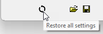
- Use this button to restore all the workshop settings to the defaults in case you want to start over from scratch :
- You will see in the lists that there are a lot of group settings that are disabled by default :
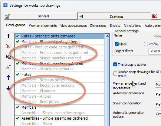
These disabled group settings were added to allow you to activate those that are relevant to you.
They serve as a starting point and can be further adjusted to your needs.
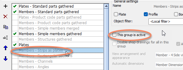
They can also give you an idea of the many possibilities that filtering into setting groups offers, so that you can learn from them and create your own if needed. - To enable or disable settings just use this checkbox while the group is selected :
- Note that the order of these settings groups is important.
Parabuild looks at the first settings group and checks whether the part matches the filters in that group.
If it does then it uses those settings. If not then it continues to the next group down the list.
For this reason it is important to have a 'Catch all' group for each type: plate, profile or assembly.
The default configuration was set up like this, in this example the catch-all group "Members" enabled, and other optional groups by default disabled: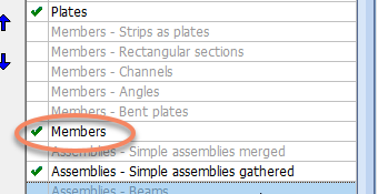
- If you want to import the version 7 bill settings into your v8 workshop settings you can use this button on the bills tab :
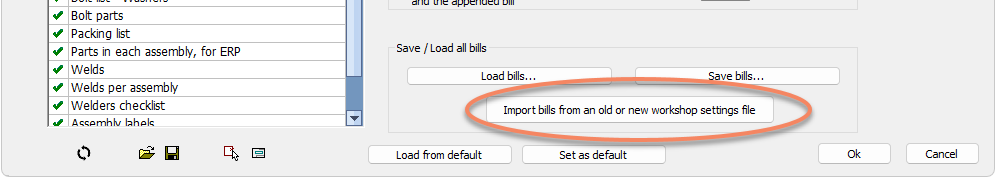
This will ask you for the location of the settings file from which you want to import just the bills.
The bills that are saved separately are stored in the folder : \Pb_Lib\Bills\
The bills that are saved along with all the other workshop settings are stored in the folder : \Pb_Lib\Workshop drawings\Settings\
Navigating the output settings dialog
The output settings dialog has 4 main tabs each of which will be explained below.

 General
The General tab contains the following settings:
- Formats
- Layer and dimension template locations
- Hatch settings - Hatch patterns can be configured based on material type or any other property of the parts.
Hatch patterns will automatically be drawn for sectioned objects on section or detail views and on isometric views that were clipped. - The accuracies of property values in bills and sheet tables
- The column titles in bills and sheet tables
Drawings
The drawings tab contains all of the settings for the shop drawings and GA drawings.

Each of these sub tabs are explained below.
1. Detail groups
This sub-tab is the primary location for the generation of part and assembly detail drawings (shop drawings).
The dialog is divided in 3 areas and each those areas is explained hereafter.
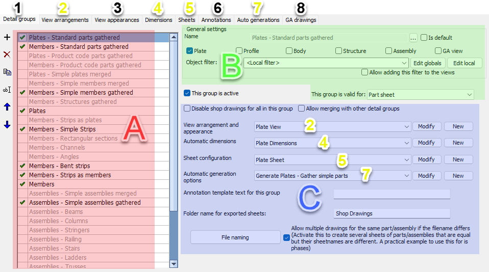
Area A
On the left side Area A there is a list of detail groups.
These are all the settings that Parabuild will loop from top to bottom when a shop drawing for a part needs to be generated.
When a detail group is selected, the settings for that group will be shown on the right side (Area B and Area C).
The greyed out groups in this list are not active so they will be ignored for the generation of sheets.
These disabled groups provide a quick way to influence the sheet generation if some of them are activated. Review the names, filters and settings of the groups to learn about the purpose of each group.
Note that the order of the items on this list has a big influence on the result of the sheet generation.
Area B
At the top Area B there is a filtering/validity section for the selected group. These settings will determine whether or not this group will be used for a specific part or assembly.
If both the part type and the object filters match, then this group will be used for the part/assembly.
Area C
In Area C you can find the drawing settings of the selected group. These settings will determine everything there is to the generation of the sheet.
It may look like there are not many settings but these settings actually refer to other named collections of named settings.
This allows us to re-use configurations across multiple groups, and to easily switch between various named settings.
The 4 main collections of settings are View arrangements and appearance (2), Automatic dimensions (4), Sheet configuration (5) and Automatic generation of sheets (7).
All of these 4 have their own sub-tab at the top. By clicking on the other sub-tabs at the top you can review and modify all of the collections.
But you can directly navigate to the settings that are in use by clicking on the Modify button next to the dropdown box. This will directly open the correct sub-tab and the settings collection within.
Then there are still sub-tabs 5, 6 and 7 which are not linked to directly by the detail group, but :
sub-tab 3 View appearance is referenced to by each view in the View arrangements (2)
sub-tab 6 Annotations is referenced to by Sheet configuration (5)
sub-tab 8 GA drawings stands on its own because it contains the settings for the creation of GA views.
Hereafter follows a more in-depth explanation of the other sub-tabs :
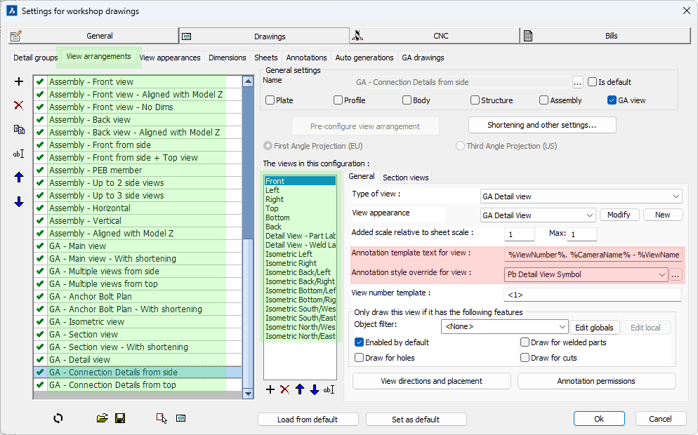
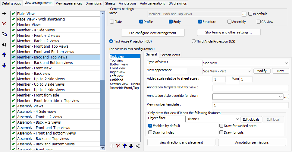 2 View arrangements
In this View arrangements list the order of the items do not influence the sheet generation but they are sortable for the convenience of the user.
The General settings determines which part and assembly types view arrangement entry is intended. This will not be used as a filter for the sheet generation but it will be used by the dialog box to determine which detail groups and GA drawings can utilize these named settings.
The other options in the dialog box are explained hereafter :
Pre-configure view arrangement
These options are not available to arrangements for plates. The options under this button will automatically arrange the views for you.
Some of the options that are available here are :
- Switch between First Angle (EU) projection and Third-Angle projection (US)
- Choose the alignment of side views and ISO view to follow the 3D model or not
- Minimum and maximum number of side views
- Activate more front/back views
- Switch between following projection rules very strictly or move section and endplate views around to use the space on paper more smartly
Note that after clicking on Ok of the Pre-configure dialog box then the views of the current arrangement will be modified and re-arranged. Any manual changes that you did to them might be lost.
Shortening and other settings
The available options are :
Extension lines grip the farthest hole - Make the extension line long so that it touches all of the hole centers, or only touch the first hole center
Draw view triangles - Draw the view triangular annotations with a view number next to each side view and also on the section view
Settings for shortening - Enable or disable shortening with a set of options for tweaking them
General
Next to the General tab all of the views are listed. The first view should be the primary view, and other views may be optionally projected off the first view, or off any other view.
For isometric views and endplate views the ordering is not important, but for section views the first is the one that will be used when a section is manually added on the page.
The available General options per view are :
Type of view - An important setting determining what kind of view this is : side view, endplate view, section view or Isometric view. This type allows Parabuild to determine appropriate behavior for this view.
View appearance - This refers to the appearance settings that need to be used for this view such as how to display holes, enable hidden lines or not, colors for lines and many more. Click on Modify to view and/or modify these settings.
Added scale relative to sheet scale - This can be used to increase the size of the view (for details) or to decrease it (Isometric views). There is a maximum scaling which is used for dimension-free isometric views during automatic sheet generation. Sheet generation will start out with the scale that you choose, and if there is more room on the page it will gradually enlarge the view up to the chosen maximum scale factor.
Annotation template text for view - Use this this template text to add an annotation underneath that view for describing the view. This is by default used for endplate and section views in assemblies, or for GA views. A general annotation for the whole part or assembly can be set in the Detail Groups tab.
Annotation style override for view - When the above template text is used then you can optionally choose an annotation style for the above annotation only. The purpose of this is to make the annotation stand out by making the text size larger or underlined, or for giving it a specific appearance such as a View Symbol.
View number template - A template can contain a static prefix and suffix, and a start number between the symbols "<" and ">". For more information see the view numbering topic. For part or assembly side views this number will typically be a static number from 1 through 4, for section and endplate views a template <A> is used which means that Parabuild should start numbering alphabetically starting from A. For GA views the default is usually <1>, and views will get an increasing number assigned based on which views were already added to the current sheet.
Only draw this view if it has the following features - These options allow you to activate or deactivate each view based on any object filter, or whether it has holes, cuts or welded parts visible.
View direction and placement - Use these settings to choose the viewing direction, the model placement on the page and the location of the view on the page for section views and endplate views
Annotation permissions - Choose whether this view should be dimensioned, and what kind of annotations can be added on the view
Section views
These settings are only available to section views and they allow you to configure the automatic generation of section views on assembly sheets.
We can influence the following parameters :.
- View direction and orientation
- View appearance including using object level overrides mentioned above
- Box size can be either absolute, or an offset relative to the objects in the section view
- Section views can be merged when view directions match and the sections are within a user specified distance
- Duplicate sections can be detected and skipped based on user preferences
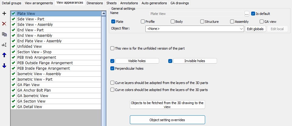
In this View appearance list the order of the items do not influence the sheet generation but they are sortable for the convenience of the user.
The General settings determines which part and assembly types each view appearance entry is intended. This will not be used as a filter for the sheet generation but it will be used by the dialog box to determine which view arrangement can utilize these named settings.
The other options in the dialog box are explained hereafter :
This view is for the unfolded version of the part - When this option is activated then this view will only be used for the unfolded view of a part, if unfolding was enabled for the part, and if the part can be unfolded.
Visible holes - Configure here how visible holes should be displayed, with the ability to choose a different display per hole type
Invisible holes - Configure here how invisible holes should be displayed, with the ability to choose a different display per hole type
Perpendicular holes - Perpendicular holes are holes seen from their side. They would be shown as 2 straight lines and optionally an axis
Curve layers should be adopted from the layers of the 3D parts - Enable this to have all the lines of an object get the same layer color and linetype as the 3D part in model space. This is typically only used on GA views. For more detailed fine-tuning such as giving only an underlayer a certain linetype you should use the Object settings overrides instead.
Curve colors should be adopted from the layers of the 3D parts - Enable this to have all the lines of an object get the same color as the 3D part in model space. This is typically only used on GA views. For more detailed fine-tuning such as giving only an underlayer a certain color you should use the Object settings overrides instead.
Objects to be fetched from the 3D drawing to the view - Configure here whether to show : invisible lines, grid lines, bolts, welds, cameras, axii, and hatches on the view
Object settings override - Use these settings to override the visibility of curves on the view. These filters can be created to target objects based on layer, material, structural type, and other properties and geometric characteristics and assign those objects a certain color, linetype, transparency, or have them be skip entirely in a specific view.
Example usages of this are to give an underlayer a grey color, making concrete slabs transparent so the parts behind them are still fully visible, or skipping certain part types from section views to unclutter them.
4 Dimensions
In this Dimensions list the order of the items do not influence the sheet generation but they are sortable for the convenience of the user.
The General settings determines which part and assembly types each dimensions entry is intended. This will not be used as a filter for the sheet generation but it will be used by the dialog box to determine which detail groups and GA drawings can utilize these named settings.
In this case the part type will also influence the dimension options that are available. Therefore the part type should be set first before attempting to change the dimension options
The dimension settings themselves have descriptions and examples in the dialog box itself.
5 Sheets
In this Sheets list the order of the items do not influence the sheet generation but they are sortable for the convenience of the user.
The General settings determines which part and assembly types each sheet entry is intended. This will not be used as a filter for the sheet generation but it will be used by the dialog box to determine which detail groups and GA drawings can utilize these named settings.
The other options in the dialog box are explained hereafter :
Format - This option is only used when this Sheets entry is used on a GA drawings group. For part and assembly sheet generation format is decided by the settings in 7 Auto generations.
Annotation settings - The annotation settings that will be used for this sheet. These annotation settings will also be stored in the sheet itself so that they can still be modified after creation on a sheet per sheet basis. Use the Modify button to directly edit the selected annotation settings.
Sheet properties - This contains the sheet number template and preferences such as LTSCALE, dimension accuracy, angle accuracy, text height for dimensions, and dimension style
Template settings - This contains the frame, bill table, title, and note that should be inserted on the sheet
Other sheet settings - This contains the clearance between views, between views and sheet edges, between parts, whether to skip a certain hole diameter, whether to skip weld symbols for a certain size, and also the typical weld sumbols for reducing the amount of weld symbols on the views
6 Annotations
In this Annotations list the order of the items do not influence the sheet generation but they are sortable for the convenience of the user.
The General settings determines which part and assembly types each annotations entry is intended. This will not be used as a filter for the sheet generation but it will be used by the dialog box to determine which detail groups and GA drawings can utilize these named settings.
The annotation settings allow us to set the annotation style and optionally override the text height for all the different types of annotations.
7 Auto generations
In this Auto generations list the order of the items do not influence the sheet generation but they are sortable for the convenience of the user.
The General settings determines which part and assembly types each auto generations entry is intended. This will not be used as a filter for the sheet generation but it will be used by the dialog box to determine which detail groups can utilize these named settings.
The auto generation settings allow us to set whether multiple parts are allowed on a single sheet, whether simple parts should be added (uncut, undrilled, unwelded), and which format and scale to be used. Parabuild will attempt to use the first format and scale in the list and if the page is too small it will attempt the next one and continues downwards until it finds a page large enough for the views at the specified scale.
8 GA Drawings
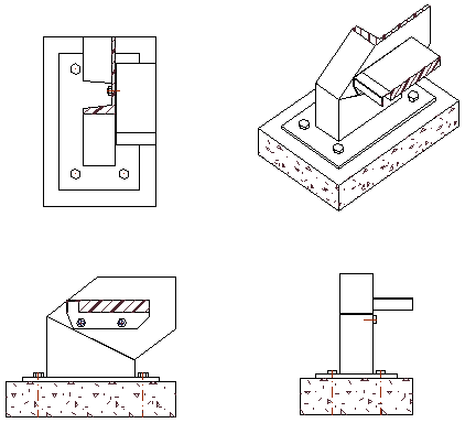
The GA drawing settings are used by the following commands/tools :
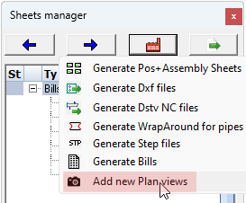
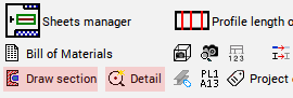
All of these tools will draw one or more new views based on a new or existing camera.
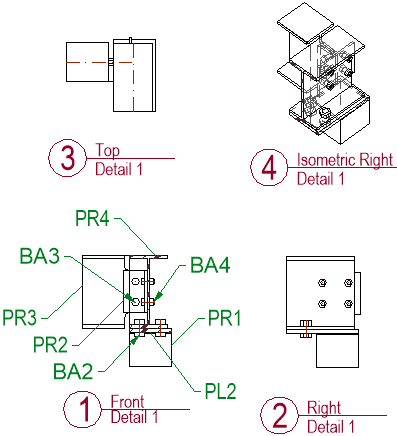
When choosing multi-view detail settings on a detail camera, a typical result looks like this :
All of the above commands will show this view preset selection and annotations dialog box :
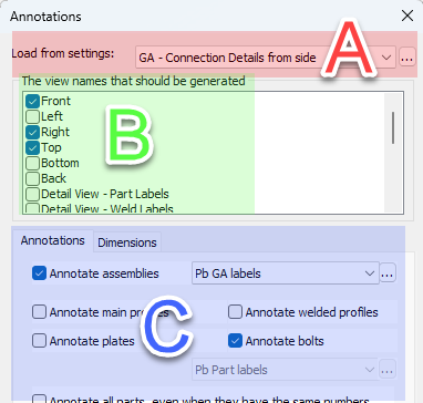
The above dialog can be fully configured with the help of the GA Drawings dialog shown below. The relations are illustrated with areas A, B and C on both dialog images.
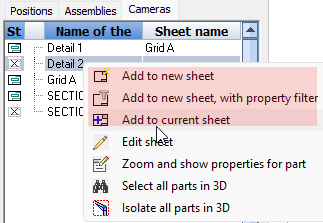
Note when Add to new/current sheet is used on a part or assembly number, then the Detail groups will be shown in the above dialog instead of the GA drawings.
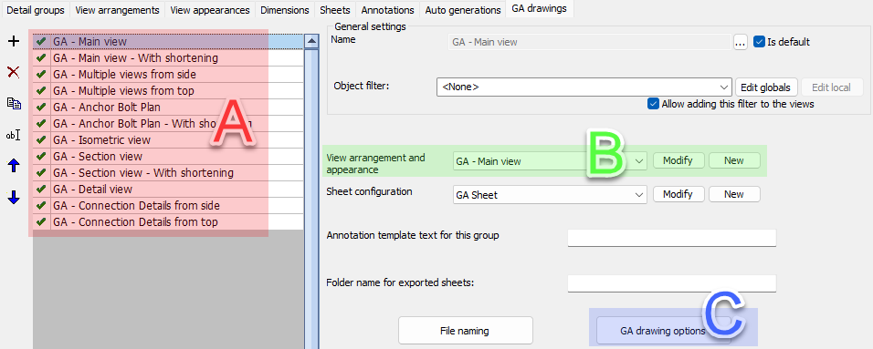 In this GA Drawings list the order of the entries are only sort-able for the convenience of the user.
A set of GA drawings were pre-created for certain commands or types of cameras such as sections, details and isometric views.
The available options per GA drawing are explained hereafter :
The General settings has the Object filter which can be added to the views that will be created. The object filter is a way to quickly filter out objects that should be shown on the view.
View arrangement and appearance - Choose the views and their appearances that should be shown as an option when one of the above tools are started. The user still has the ability to enable or disable some views. Click on Modify to go directly to the chosen settings
Sheet configuration - This contains the sheet configurations such as format, template files and annotation styles. Click on Modify to go directly to the chosen settings
Annotation template text for this group - In case an annotation below the set of views is wanted then this template text can be entered
Folder name for exported sheets - When the sheet is exported as a dwg file or pdf file then it will be written in the provided sub folder name
File naming - Here we can change the sheet name as well as the sub-folder that should be used by the sheets manager.
GA drawing options - Here we can configure the default format and scale, whether the views should be shortened, whether annotations and dimensions should be added. Note that it is possible to enable or disable annotations on a per view basis in the settings B View arrangement and appearance. There we have the Annotation permission settings which will permit or forbid annotations per view.
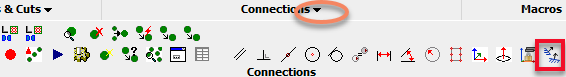
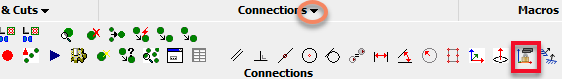
CNC
This tab contains all of the settings for the creation of CNC files.
![]()
For each type of CNC there is a sub tab but there is also a main CNC group tab which drives the generation of CNC files :
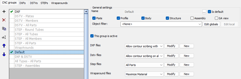
The greyed out groups in this list are not active so they will be ignored for the generation of CNC files.
These disabled groups provide a quick way to influence the CNC file generation if some of them are activated. Read the names of the groups to learn about the purpose of each group.
Note that the order of the items on this list has a big influence on the result of the CNC files generation.
If the part matches the filter in the General settings of the group then the group will be used for that part.
If it does not then the next group in the list will be used until a group that matches is found.
Each of the 4 CNC file types can be chosen per group. Each of them refer to the sub-tabs DXFs, DSTVs, STEPs or Wraparounds.
It is possible to create only a single type of CNC a single CNC file per part when this is the intent. For example, for plates you may only want DXF files, and for members you may only want DSTV files. In this case make an entry that filters only for the objects you want to set, configure the correct CNC type, and set the other types to <None>
Sometimes this is not desirable, for example for round tubes you may want both a DSTV and a wraparound. If this is the case then you would need to make an entry for round tubes that sets both types.
Bills
This tab contains all the settings for the reports generation.
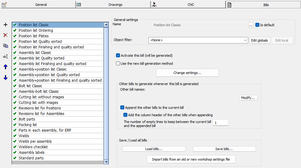
The list contains all of the bills that can be generated, but not all of them are active.
When a bill is activated (see checkbox) then the bill will become visible in the sheets manager.
Managing views and cameras
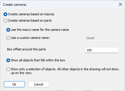
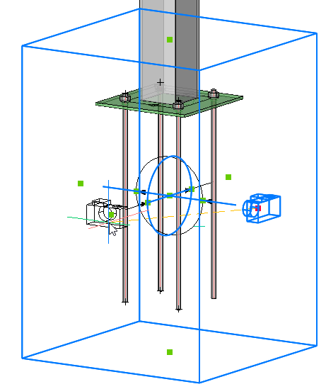
Automatic creation of cameras in the model
Command name : PrB_CreateCameras
 This command was added for automatically creating cameras in the model based on macro spheres or a manual selection of parts.
This is especially useful for creating connection detail views.
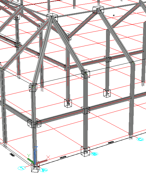
When we choose Create cameras based on macros then a box camera will automatically be created for each selected macro.
When we choose Create cameras based on parts then a camera will be created that fits the parts selection.
If the chosen primary view direction was not ideal, a quick grip stretch operation is enough to change the viewing direction. See topic Manipulating a camera in model space
Manipulating a camera in model space
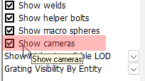
Cameras in model space can all be shown or hidden with this checkbox in the Visibility Manager :
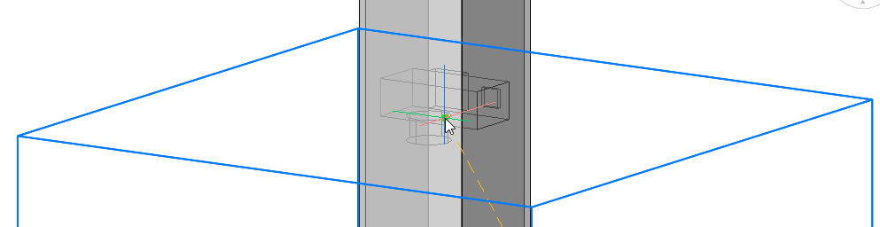
To modify a camera in model space we need to select it after which 11 grip points are displayed.
The 6 grip points in the middle of each face of the box are the most important ones :
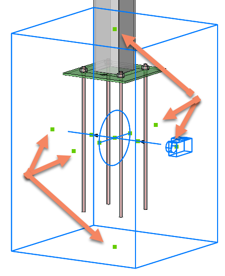
To swap the viewing direction of the camera we need to first click on the grip that is on the camera :
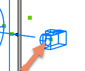
Then move the cursor towards any of the other 5 grips on the faces of the box. This will cause the camera to switch position :
It is easier to do this when the ORTHO tool is disabled.
We can do the same thing for any face on the box. For top and bottom view it is also possible to influence the rotation of the camera by moving the cursor around the grip point. You may have to zoom in more if the 4 view rotations are not presented :
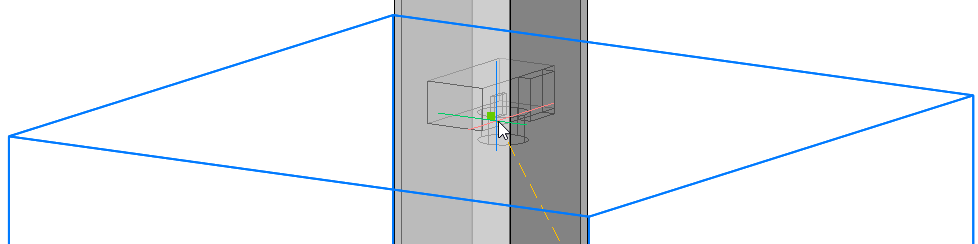
When the desired camera viewing direction is shown on screen then just left-click to confirm the new position.
 Callouts, cameras inside views, sheet and view numbers
A view callout is an annotation on a section or detail camera that displays view number and sheet number (and optionally additional information). It tells the person who reads the drawing where to find the view that is referenced there.
To make this annotation possible a view can contain cameras that may be printed or not printed.
Each view and each sheet get a number and a name so that the annotation can display these numbers.
The camera inside the view is linked to a camera in model space, which in turn is linked to all of its views. This is how the annotation can show the view and sheet numbers that are being referenced.
We will explore each of these different steps in the process hereafter :
Automatic assignment of Sheet and View numbers
Sheets and views are automatically numbered based on a template string that allows you to choose the prefix, suffix and start number.
The numbers are assigned sequentially, based on time of creation, but they can be updated later.
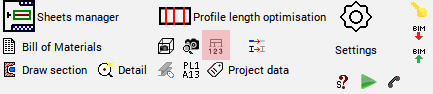
Automatic assignment of sheet numbers is determined by the template string that can be found in the workshop settings :
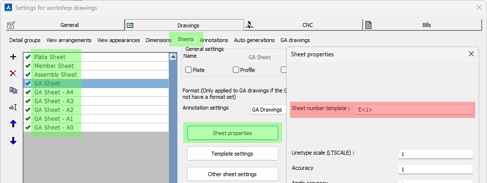
The links for getting to the location of the sheet number template text are highlighted in green
Automatic assignment of view numbers is determined by the template string that can be found in the workshop settings :
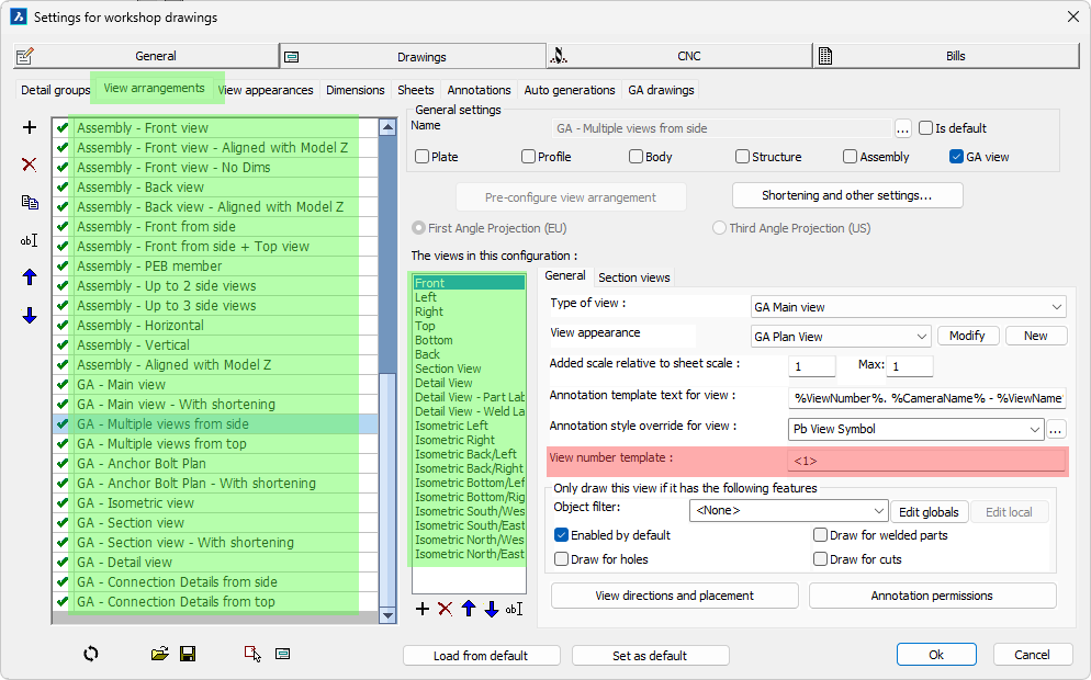
The links for getting to the location of the view number template text are highlighted in green
Some more information about the view or sheet number template text
For most sheets and views the text template is <1>. The number between brackets tells Parabuild that a number should be used starting from 1.
Some example template texts are :
- If the template is <100> then the start number should be 100 so the first 99 numbers will not be used.
- If the template is <A> then the result is A, and the next ones will be B, C, etc... This is typically used for section views on assembly drawings.
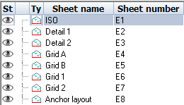
- If the template is D<1> then the result will be D1, D2, etc...
- If the template is GA<1> R2 then the result will be GA1 R2, GA2 R2, GA3 R2, etc...
 Renumbering sheets
Once a sheet has been created, the number can still be modified afterwards with the following method.
The sheet number can also be used inside the sheet name, which gives you an additional option for your sheet naming strategy.
The sheet number can be changed in the sheet properties which is accessible by right-clicking on a sheet in the sheets manager.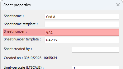
Note Whenever you change a sheet number manually in the properties Parabuild will renumber other sheets to avoid conflicts when needed.
Renumbering views
The number of existing views can be changed on a view per view basis in the View properties :
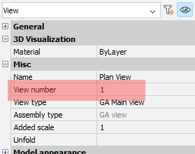
When you change a view number this way then Parabuild may change the view numbers of other views on the sheet automatically in order to avoid same-number views.
If there are many views on the sheet then it may become hard to set the view numbers the way you want because of this.
The view renumbering command resolves this issue.
View Renumbering command
Command name : PrB_RenumberViews
This command allows you to change the sequential numbering of the views while still respecting the number text template of each view.
The first thing this command asks for is the start number for the first view.
After that you should select each view that needs to be renumbered starting with the view that needs to receive the lowest number, and each view that you select after that will get a higher number.
It is not necessary to select all the views on the sheet. The views that you did not select will be untouched if their view numbers do not conflict with the new view numbers that were assigned during this command.
Note Whenever you change a view number in the properties or through the numbering command Parabuild will renumber other views to avoid same-number views when needed.
 Cameras inside views
Cameras on the model can be automatically inserted into main views during creation, or they can be pulled in while editing the view.
Which cameras are automatically added to a view is determined by this settings in the output settings :
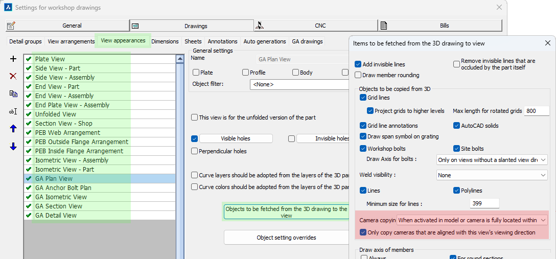
The links for getting to the location of the camera copying are highlighted in green
For existing views it is possible to add more cameras to the view with the manage cameras command :
Manage cameras inside view command
Command name : PrB_ManageCamerasWithinView
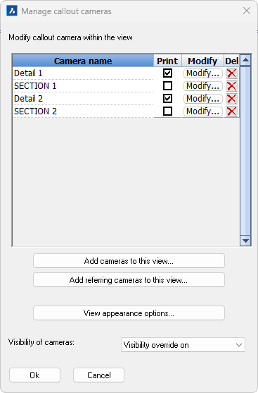 This command is also accessible by double-clicking on a view, which will directly open the same manage cameras dialog box :
The purpose of all the items on the dialog are explained hereafter :
At the top we can see a list of all the cameras that are contained within the view.
Next to each camera name we can perform the following actions on the camera :
- Print camera - Enable this option if you want the camera to be visible when the sheet is printed.
- Modify camera - This button brings up the camera modification dialog of which the most important options are :
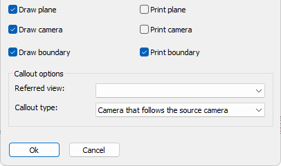
- Draw plane/camera/boundary - Enable the geometries of the camera that you want to see when the view is not in print view mode
- Print plane/camera/boundary - Enable the geometries of the camera that you want to see when the view is in print view mode
- Callout referred view - When the camera was used to create several views, you can change the view that should be referred to. This referred view will then be used by annotations on the camera to know what view number and view name to display
- Callout type - This allows us to change the type of camera. The following types are available :
- Camera that follows the source camera - This is a camera that will move automatically when the model space camera linked to it moves (the move will happen on each view refresh)
- Referring camera that can be moved - A referring camera is still linked to a model space camera but the position of this camera is not managed by Parabuild but by the user
- Referring camera that can be moved and re-oriented - A referring camera is still linked to a model space camera but the position as well as the viewing direction of this camera is not managed by Parabuild but by the user
- Delete camera - To remove cameras from this view, this does not delete the original camera in the model. If you delete a camera that is within the view limitations of the current view then the camera might be re-inserted automatically the next time that the view is refreshed, depending on view settings.
The bottom of the dialog contains the following actions and settings :
Add cameras to this view - This will open a dialog allowing you to add more cameras to this view. This lists only the cameras that are at least slightly within the view's extents. This will create a normal camera whose position stays linked to the model space camera at all times.
Add referring cameras to this view - This will open a dialog allowing you to add more cameras to this view. It will list all of the model space cameras, even those that are far away from this view's extents.
This will create a referring camera whose position is not linked to the model space camera but instead is determined by you.
After selecting the camera that you would like to insert you also have to choose the view to which you want the new camera to refer to.
Lastly, you have to choose the location center point for the new camera.
The new camera will immediately be drawn on the view after that, end the process will be repeated for adding an additional referring camera to the view. Press the <Esc> button to stop adding cameras.
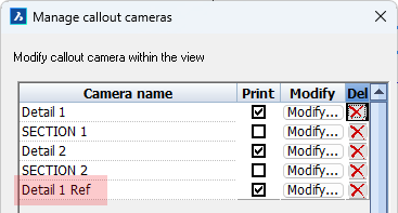
The new camera receives the same name as the model space camera but with Ref added to it to differentiate it from other cameras
View appearance options - This button is simply a shortcut to the advanced properties of the view
Visibility of cameras - Some cameras we want to print such as detail cameras and other we do not want to print such as section cameras.
However when a camera is not printed then the view does not display them making it hard to annotate that camera.
By activating this option we can show all cameras anyway independently of their print status.
The cameras that are set to no printing will not be printed even if the view is set to show all cameras with this setting.
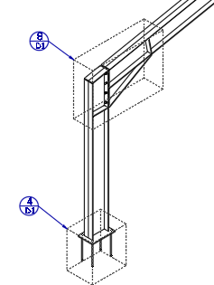
Referring cameras allow you to create many references to the same detail view for cases where the details are the same :
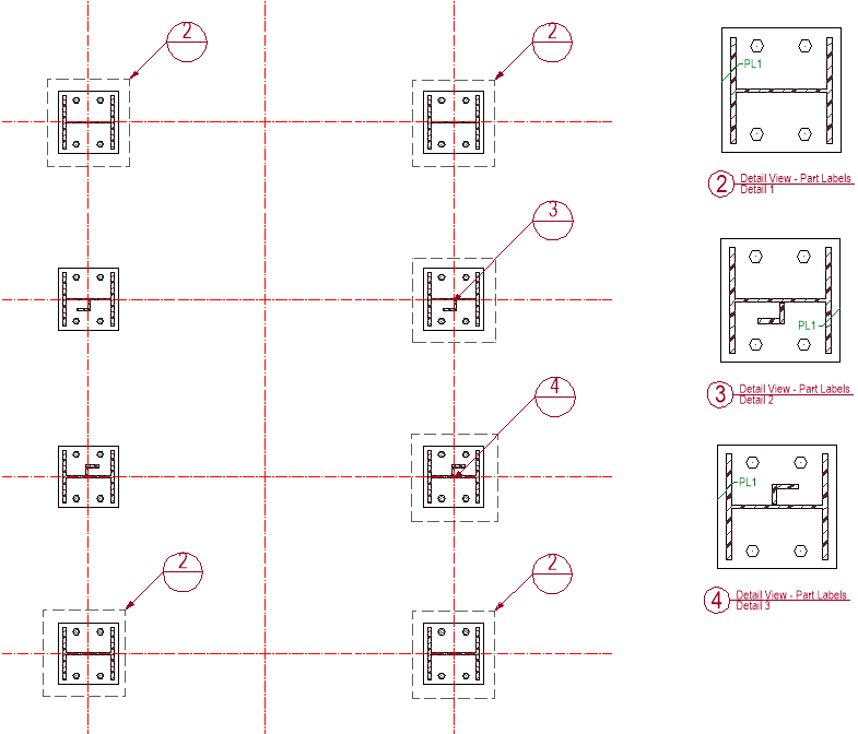
An example usage of referring cameras. There are 3 referring cameras for view number 2 on this view. It is the drafter's responsibility to see and know the difference in details such as with views number 3 and 4.
Note Parabuild does not check whether the parts within the referring camera in any way resembles the parts displayed in the referred view. It is the drafter's responsibility to make sure that the references they make matches the parts in the referred view.
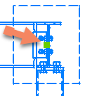 Moving a referring camera on the view
To move a referring camera the view needs to be selected first.
The referring cameras will have a grip point in the center of the camera.
Simply click on this grip to move the camera to any other location on the view.
Non-referring cameras can't be moved because Parabuild keeps their position locked to the position of the model space camera.
View symbols and callouts
View symbols and callout annotations are automatically drawn by the tools that draw plan views, section views, detail views, and adding cameras to a view, if the settings for the view and annotation style are configured that way.
The view symbol contains the view number, the view name and the camera name.
The callout annotation contains the view number above the horizontal line and the sheet number below the horizontal line.
If the referred view is on the same sheet as the annotated view then the sheet number field is empty.
View symbols and callouts will update automatically when view numbers or sheet numbers change.
|
|
View symbol example |
Section view symbol example |
|
|
Detail callout example |
Section callout example |
The annotation styles and groups themselves are explained in the Annotations topic.
The locations where the annotation groups or styles are configurable are explained hereafter :
Configuring view symbols
View symbol annotations can be configured per view.
This allows us to give a section view a different symbol than a detail view.
The links for getting to the location of the view symbol configurations per view are highlighted in green
If the above annotation Template text field is empty, then the template text configuration inside the annotation style will be used.
If the above Annotation style is empty then the Annotation label style of the sheet will be used for the view symbol.
The sheet's view label style can be found here :
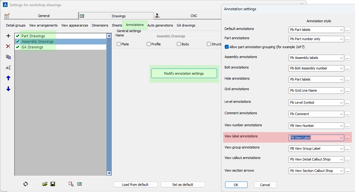
The links for getting to the location of the default view label style are highlighted in green
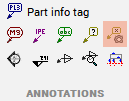
Manually drawing a view symbol
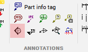
There is no direct command for drawing a view symbol but we can use this generic annotation command to draw view symbols manually :
Command name : Prb_Tag
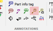
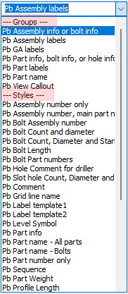
The first thing this command asks for is which annotation style of group you want to use to draw an annotation.
Choose the group Pb View Symbol :
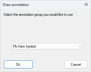
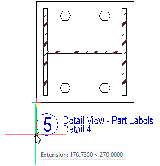
Then simply select any point on the view that you want to annotate, after which the symbol can be drawn.
Manually drawing a callout annotation
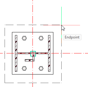
Command name : (Prb_TagGroup "Pb View Callout")
After starting this command you are prompted to select a point on the view.
Normally this command expects you to select the center of the camera that you want to annotate.
But when the extents box of a detail is drawn on the view then we can simply move the cursor over these edges and the OSNAP endpoint will then snap to the center of that camera.
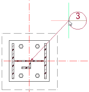
Once you correctly selected the center location of the camera you can then select the location of the callout itself :
|
|
Choosing the center point of the camera |
Choosing the location of the callout camera |
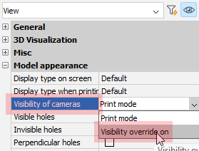 Some cameras such as section views are by default not drawn on the view. You can set the property Visibility of cameras to Visibility override on to make it possible to see and annotate all cameras in the view. This does not influence the visibility of the cameras when the view is printed.
Annotation styles and groups
Command name : PrB_TagSettings
 Annotations styles and Annotation groups are now split.
Annotations no longer need to be part of a group in order to be used when drawing an annotation, and multiple groups can refer to the same annotation.
This makes annotation styles much easier to configure.
Note that only groups have filtering features for letting Parabuild automatically choose a style based on filtering rules.
In many locations throughout the Parabuild settings there are dropdown boxes for choosing an annotation style or group to be used.
Here both the groups and the individual styles will show up in the same dropdown, grouped together by type.
All the default Parabuild style names that come with a fresh installation of Parabuild now start with "Pb ", to differentiate them from user styles.
Annotation groups
Annotation groups are used to let Parabuild draw different annotations based on filters.
For example when a hole is selected we may want a completely different annotation than when a part is selected.
The annotation groups have the following capabilities :
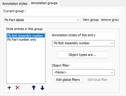
Style entries in this group - This list contains all of the different styles that this group supports. The minimum is 1. Use the up and down button to change the order of the items in the list. The order of the items does matter because the first item in the list that positively matches filter values will be used to draw the annotation.
Annotation style of this entry - Choose the annotation style that is to be associated with this entry
Object types are - Choose one or several object types that are required for this annotation entry to be used. Object types can also be holes or assemblies.
Object filter - Choose the optional object filter that is required for this annotation entry to be used. This is a filter in addition to the above object types.
Annotation styles
Annotation styles simply store all the properties that the new annotations should receive.
Highlighted here are the new properties in this version:
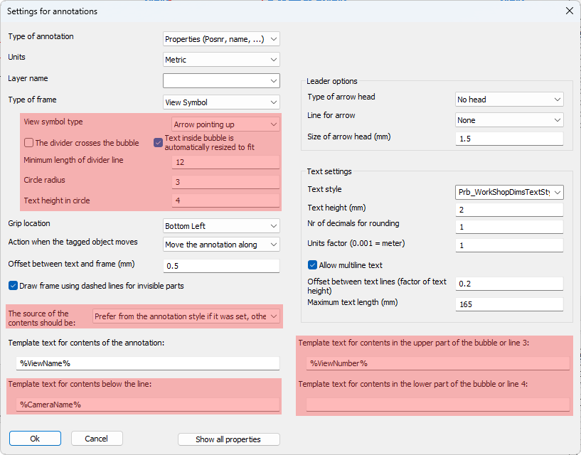
The annotation style has the following new properties :
- View symbol type - Whenever the frame type View Symbol was activated this option will become available allowing us to choose the view symbol with an arrow in any of the 4 directions. An example view symbol with arrow down is :
If the option without arrow is drawn then the symbol looks like this :
- The divider crosses the bubble - This option enabled looks like this :

This option disabled looks like this : - Text inside bubble is automatically resized to fit - When this is enabled, the size of the text inside the bubble will be decreased to fit the text inside the circle.
- Minimum length of divider line - Use this to increase the divider line's length in case no text is shown on the line such as with this example :
- Circle radius - Choose the radius of the bubble here (paper units)
- Text height in circle - Choose the default text height of the text inside the bubble here (paper units)
- The source of the contents should be - When there is an annotation template in both the shop drawing settings AND the annotation style, you can now configure which gets preference
- Template text for contents of the annotation - This is the normal text that any annotation has. In the case a divider line was enabled this will be the text above the divider line
- Template text contents for contents below the line - In the case a divider line was enabled this will be the text below the divider line
- Template text contents for contents in the upper part of the bubble or line 3 - When a bubble is activated this will be the contents of the text in the upper part of the bubble
- Template text contents for contents in the lower part of the bubble or line 4 - When a bubble is activated this will be the contents of the text in the lower part of the bubble
 Rods
Rods
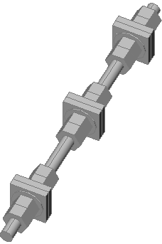
It is possible to draw simple and complex rods with the same Parabuild tools that are used for drawing bolts, nuts and washers.
A rod can tighten up to 3 groups of materials where a normal bolt can only tighten 1 group of material. A maximum of 4 parts can be activated on each side of the material for a total of 8 parts per tightening group. A group can also be a standalone combination of (square) washers and nuts such as for anchors embedded in concrete. In this scenario the group does not fasten any plates together.
In the rod assembly settings we can choose the type of part to be used in each position, and when drawing the actual rod we can activate or deactivate individual parts as needed.
Drawing new rods and configuring rods is explained hereafter :
 Drawing rods or standalone nuts
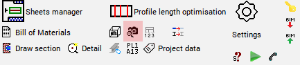
Use any of the existing tools to draw new bolts. Many of them are highlighted here :
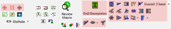
Once the bolts are drawn you can choose a bolt assembly that contains a rod or standalone nut.
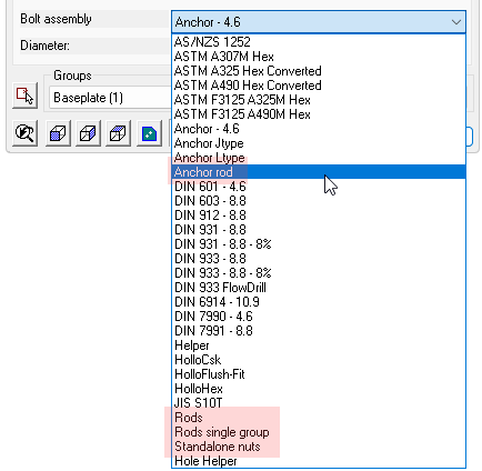
In the default installation the rod and standalone nut assemblies rods are called Anchor rod, Rods, Rods single group, and Standalone nuts :
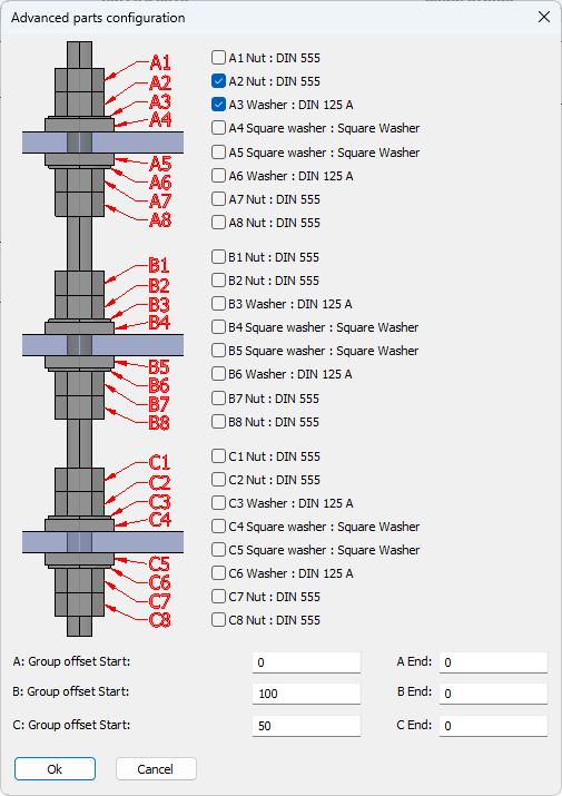 Once the rod or standalone nut is drawn we can change the parts in the Advanced Parts configuration dialog.
This dialog is available from the Advanced button in the macro dialog or from the Advanced parts configuration property of the bolt.
In the center of this dialog we can enable or disable the parts around the tightening groups.
However it is not necessary for these groups to tighten something.
In the case of an embedded anchor rod we may want the rod to embed a square plate which can be activated as a square washer. In this scenario there is no need to draw additional plates in the model.
The square plate will be listed in the reports as a square washer as part of the anchor rod assembly, the name for the square washer can be adapted in the Bolt Parts Library.
When we are activating the parts of a tightening group that is not tightening anything then we can use the group offsets at the bottom of the dialog to position the tightening group.
The start offset is the offset measured from the start of the rod.
The end offset is the offset measured from the end of the rod.
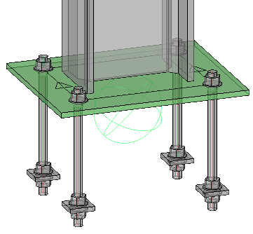
This is an example of an anchor rod with the last tightening group having a square washer and two nuts activated. The C Group Offset End was used to position the square washer and nuts relative to the ending of the rod.
Nuts and washers can now be drawn without a base bolt. We can still use the same bolt object for this which gives us all the advantages such as ease of drawing, automatic hole creation, and unified handling in reports and exports.
Standalone nuts could be solitary, or a combination of nuts and washers in case they are to be used with custom-created bent rods.
Configuring rods or standalone nuts
Rod and standalone nut assemblies can be configured in the Bolt Assemblies dialog.
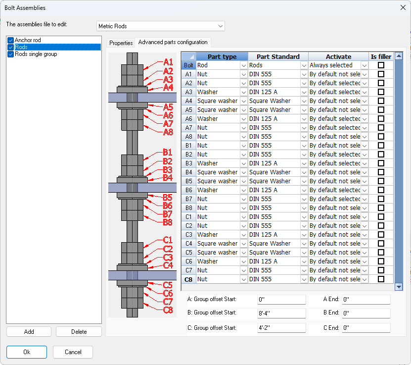
On the Advanced parts configuration tab it is possible to choose what part type should be used on each position, and whether each part should be activated by default or not the first time that a rod is drawn.
A condition for being able to add these part types is that the bolt part types already exist in the Bolt Parts Database.
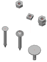
The following part types can be added to the Bolt Parts Database and can be used as part of a bolt assembly:
Example |
Description |
|
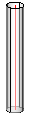
Rod |
|
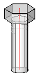
Hex head bolt |
Square head bolt |
|
|
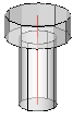
Cylinder head bolt |
|
Countersunk bolt |
|
Domed head bolt |
|
Rod type None |
|
Nut |
|
Square nut |
Washer |
|
Square washer |
|
|
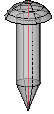
Sharp point length |


Prod uct codes
Product codes can be used to uniquely identify items that may be standardized or available off-the-shelf and have an associated code. Product codes can be proprietary formats, or they can be standardized like UPC or EAN codes.
When a product code is needed for reports or annotations, Parabuild will look it up in one of these sources:
- The product code property of the part, if it was set. This property can be automatically assigned using the Standard Parts Library
- For bolt assemblies the product code property in the Bolt Assemblies library
- For bolt parts the product code property in the Bolt Parts library
- For profiles the Product code in the section table of the profile
- Lastly, the Product code tables that are stored in the library
The above sources will be iterated in the same order. The first source for which a product code was found will be used.
The product code is retrieved whenever the columns PbBillColProductCode or PbBillColAssemblyProductCode are used in regular bills or profile length optimizer bills.
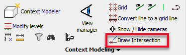
New commands and tools
New command : Draw intersection between 2 geometries
Command line name : PrB_DrawIntersection
After selecting 2 sub-geometries the command will draw a planar helper entity where the 2 geometries (apparently) intersect.
The goal of this command is to let you find complex intersections without the need for changing UCS or using Object snaps.
The fact that the new plane geometry is constrained with a macro is also an advantage because the intersection location will be re positioned automatically after a change to one of the objects that you used to draw the intersection.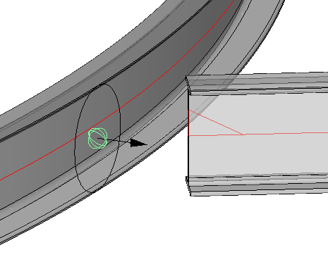
For now this command only supports points, lines, planar surfaces, and cylinders.
The following combinations are currently supported :
- Point and line (selection order does not matter)
- Point and Plane (selection order does not matter)
- Line and Plane (selection order does not matter)
- Line and Line if the lines are not parallel. This is a special case because this combination will cause 3 helper planes to be drawn.
This combination will also work when the lines do not actually intersect. It will draw the apparent intersection in that case.
The selection order has a small influence on the position of the 3 helper planes that are drawn. They will be coincident with the first line that is selected. - Point and cylinder. The position on the cylinder that is closest to the point will be drawn (selection order does not matter)
- Line and cylinder if they are not parallel. This will draw a plane object with the origin on the intersection and the direction tangent with the cylinder. (selection order does not matter)
New command : Designate object as helper geometry
Command line name : PrB_DisableObjectsForOutput
This command allows you to disable an object so that it will not be shown in any output be that bills, workshop drawings or GA drawings.
This command will do different things depending on whether the selected object is owned by a macro or not :
- When the object is owned by a macro the command uses the macro to hide the object from model space. In this case the object will never be visible anymore and it will not appear on any generated output documents.
- If the object is not owned by a macro then the settings of the object are modified so that it does not show up on any generated output documents.
This tool might not be the best solution if you want to use this tool to disable output for an object that acts as an existing structure.
This tool might also entirely hide the object and will also disable the visibility of the object on General Arrangement drawings.
In this case you should instead change the Output method properties of the object.
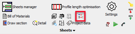
Additions for the optimize command
The profile length optimization command calculates an optimized solution for cutting profiles from readily available stock sizes.
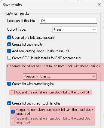
The optimizer command can now write a full report of the items by merging the chosen stock length report with another report containing the parts that were not included in the stock lengths. The complete report could for example be used for advance bill of materials.
The optimize command can now use a filter or a selection to limit the amount of parts that are displayed in the primary dialog box.
New global settings
This is an overview of all the new settings that were added to the Parabuild global settings dialog box.
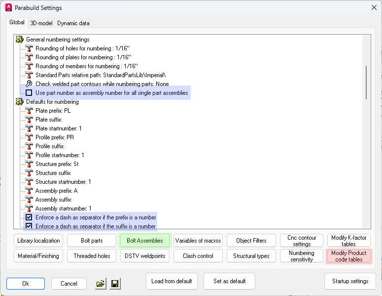
These are the locations of the new settings that are explained below
Generic numbering options
Use part number as assembly number for all single part assemblies - When this is enabled and an assembly is comprised of just 1 part, then that part's number will be used for the assembly number
Enforce a dash as separator if the prefix/suffix is a number - When this option is enabled and the prefix is 4 and the number is 3, the resulting number will be 4-3. When the option is disabled the resulting number would be 43
Default assembly name/description - This can be used to give an assembly a name. The default is to combine the assembly structural type with the main part name.
These properties can be a template string combining any number of properties, such as the structural type, material, main part name, etc...
This property can also be automatically assigned using template drawings or by structural type classification.
When the property was not individually set in the properties of the part then the default template string is used for that assembly. This default can be determined by the user in this dialog box.
When neither the assembly property or drawing default was set, the name of the main part is used instead.
The names PbColMarkName and PbMarkDescription can be used in bills and annotations to display the value of this property.
The name value will also be shown when the property PbColName is used in a bill or annotation.
More bolt assembly options
The most notable change is the Advanced parts configuration which allows us to draw rods and standalone nuts. Look at the Rods topic to learn more about these features.
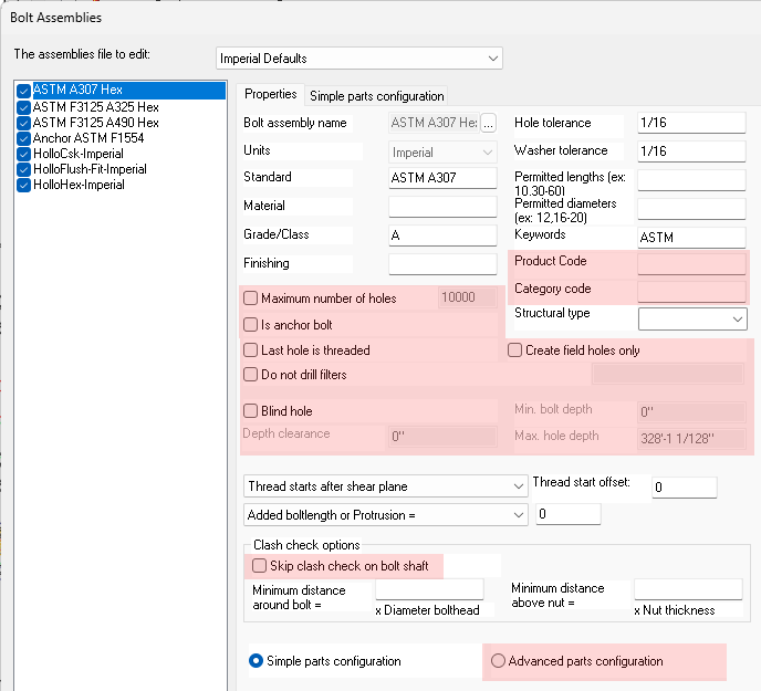
Aside from that the following new options were added to the bolt assemblies :
- Product code
- Category code
- Is anchor bolt
- Maximum number of holes
- Last hole is threaded
- Do not drill filters
- Create field holes only
- Blind hole
- Skip clash check on bolt shaft
- Minimum distance around bolt / above nut : These are 2 overrides of the 2 clash check settings that are configurable in the Global settings.
For all of these new options the same properties exist for the bolt or holes.
The bolt library options allow you to set the default property value of the bolt or holes when the bolt is created.
Modify product code tables
Product codes can be used to uniquely identify items that may be standardized or available off-the-shelf and have an associated code. Product codes can be proprietary formats, or they can be standardized like UPC or EAN codes.
The product code table is just one of the 5 ways to assign product codes to parts. Look at the Product codes topic to learn more.
The product code table itself is a way to let Parabuild automatically assign product codes to objects based on a set of property values that you've set.
This task could as well be done by classification or other tools in Parabuild, but an important reason why these tables exist is because the tables can also assign product codes to parts that do not really exist in the 3D model.
This is the case with the Profile Length Optimization command, which has stock lengths of parts which we do not draw. The optimize command still uses these part lengths and when reports are generated in the optimize command it will lookup these product tables to find the product code for the stock length of the part.
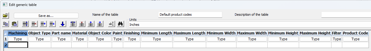
In the table one product code van be entered per row. The product code is entered in the column with the name Product Code.
All the other columns are a way to filter the parts so that the correct part gets assigned the product code.
When a filter is not required you can simply leave the field of that column empty.
But it is the drafter's responsibility that the filtering is done adequately enough so that the product code does not get assigned to the wrong parts.
For each part, the first line that matches the filters is chosen. Therefore more lines with detailed filters should be higher in the list, and more generic, "catch-all" lines should be lower.
The column names carry a name but it is the column order that defines the filters. These columns should therefore not be removed, added to or re-arranged.
The product code table has the following columns :
- Machining - This is a boolean value that should be set to 1 or 0, or empty if the filter is not to be used. A part that needs machining is a part that has cuts, and/or holes, and/or non-rectangular plates.
- Object type - Enter one of these text values to filter on object type : Bolt Assembly, Bolt Part, Plate, Member, Body, Structure
- Part name - Enter the name of the part which is the section name for members, or the plate or bolt name. For this field it is permitted to use a wildcard f.e. IPE*
- Material / Object Color / Paint / Finishing - These fields correspond to the same-name properties of the parts. For these fields it is permitted to use a wildcard f.e. IPE*
- Minimum length/width/height - Specify the minimum length/width/height of the part. For bolts the width is the diameter. For plates the height is the thickness. Leave the field empty if the filter is not required.
- Maximum length/width/height - Specify the maximum length/width/height of the part. For bolts the width is the diameter. For plates the height is the thickness. Leave the field empty if the filter is not required.
- Filter - Enter an Object Filter name here if you want to use a custom way to filter on parts properties.
- Product code - The actual product code that needs to be assigned if all filters on the row are valid. This field is required.
 Bolt assembly and bolt part numbering
Parabuild can automatically number bolt assemblies and their individual parts: base bolt, nuts and washers.
Different prefixes and start numbers can be chosen for assemblies and each bolt part type. If enabled, bolt numbering will automatically run during the existing numbering commands.
Numbered bolt assemblies and parts can be used in annotations and bill columns, and can be useful on shop drawings (for shop bolts), GA drawings (field bolts), for shipping and on-site use for easy labeling and identification.
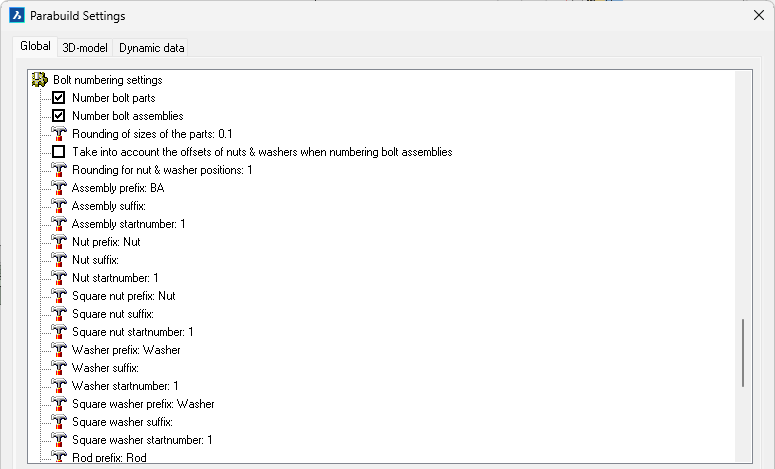
At the end of the settings dialog most of the bolt numbering settings are shown.
The following settings were added :
Number bolt parts - When this is activated all the bolt parts will receive a part number. A bolt part is for example a base bolt, a nut or a washer
Number bolt assemblies - When this is activated all the bolt assemblies will receive an assembly number. A bolt assembly is a bolt together with all of it's washers and nuts as it is drawn in the 3D model. If 2 bolt assemblies have a nut of a different standard or a different amount of nuts then they will get a different assembly number
Rounding of sizes of the parts - The rounding that should be applied when 2 bolt parts are compared to check if they should get the same bolt part number
Take into account the offsets of nuts & washers when numbering bolt assemblies - When this is enabled then not just the bolt parts are used to check whether assemblies are equal, but also the position of the bolt parts on the shaft of the bolt
Rounding for nut & washer positions - When the above option is activated, then this setting will be the rounding that should be applied when the offsets of 2 bolt assemblies are compared
The below 3 settings are repeated per assembly and each bolt part. We will explain them just once because they all have the same purpose but for different parts.
A bolt part or assembly number is comprised of 3 parts : the prefix, the number and the suffix.
For example :
BA 4 X
prefix xx xx - Specifies the prefix before the number
xx startnumber xx - Specifies the start number for the number. If the number is occupied the next available number will be used.
xx xx suffix - Specifies the suffix after the number
New properties
The following new properties were added for profiles, plates, structures, volumes and bolts :
- Assembly name/description override - This property is useful to be used in bills. These properties can be a template string combining any number of properties, such as the structural type, material, main part name, etc...
This property can also be automatically assigned using template drawings or by structural type classification.
When the property was not individually set in the properties of the part then the default template string is used for that assembly. This default can be determined by the user in the Global settings dialog box.
When neither the assembly property or drawing default was set, the name of the main part is used instead.
This property is accessible from the advanced properties dialog box for profiles, structures and volumes
The names PbColMarkName and PbMarkDescription can be used in bills and annotations to display the value of this property. - Product code - All volume entities including bolts now have this property.
For bolts this represents the assembly product code. bolt part product codes are set in the Bolt Parts Library.
Product codes can be used to uniquely identify items that may be standardized or available off-the-shelf and have an associated code. Product codes can be proprietary formats, or they can be standardized like UPC or EAN codes.
This property is just one of the 5 ways to assign product codes to parts. Look at the Product codes topic to learn more.
The name PbColProductCode can be used in bills and annotations to display the value of this property. - Assembly product code - All volume entities excluding bolts now have this property.
Product codes can be used to uniquely identify items that may be standardized or available off-the-shelf and have an associated code. Product codes can be proprietary formats, or they can be standardized like UPC or EAN codes.
This property is just one of the 5 ways to assign product codes to parts. Look at the Product codes topic to learn more.
The name PbColAssemblyProductCode can be used in bills and annotations to display the value of this property. - Category code - The category code can be used for a number of purposes but an example is for assigning a cost category to the parts in the estimation phase.
The name PbColCostCategoryCode can be used in bills and annotations to display the value of this property. - Assembly category code - The same as category code but it assigns a code at assembly level
The name PbColAssemblyCostCategoryCode can be used in bills and annotations to display the value of this property. - Object color - This would be the color of the part as it is without paint, as you want it to show up in reports. This is particularly used for non-steel material where the material itself can have a custom color and paint is not applicable.
The name PbColObjectColor can be used in bills and annotations to display the value of this property. - Color group - This property can be used to group parts into color groups as an additional way to categorize the objects. The color groups are usable in filters and are especially useful to be used in the color schemas in the Visibility manager.
This property is accessible from the advanced properties dialog box. This property is available to macros, arrays, bolts, plates, profiles, structures, and volumes. - Skip clash check - When this option is enabled then the object will not take part in the clash checking routine. Care should be taken when using this function because failure to erect the structure may occur if clashing elements are allowed.
This property is accessible from the advanced properties dialog box for plates, profiles and volumes. For bolts it is available directly on the properties panel. - Ignore clash volume - Enter the volume that the clash control should ignore when the object is clashing with another object. If the clash volume is smaller than the given volume then the objects will not clash. If the volume is larger then the objects will be designated as clashing.
This property is accessible from the advanced properties dialog box. This property is only available to plates, profiles, structures and volumes. - Minimum bolt length - With this setting we can let Parabuild increase the bolt size beyond the normal length that Parabuild chooses automatically. This setting is particularly useful to be used on anchors, because with this we can influence the depth of the anchors that needs to be embedded. Set this value to 0 if you do not want to influence the length and let Parabuild decide the length based on the tightened parts, bolt parts and offsets.
If Parabuild does not increase the bolt length to the minimum that was set then the bolt Bolt Parts Database does not contain the bolt length that is requested.
This property is also available in the bolt settings of any macro that draws bolts. This property is only available to bolts/rods. - Only draw holes in parts that are used by the module that draws the bolt - This option is useful to those that create custom macros. When enabled, the bolt will only add holes to parts that are flexible, rigid or fixed geometry in the module. This allows you to limit the normally very flexible hole drilling behavior of bolts. You can add dummy constraints to a part if you want that part to also receive holes from the bolt.
This property is accessible from the advanced properties dialog box. This property is only available to bolts. - This is a helper profile for a macro that uses it to draw several other profiles - This option is useful to those that create custom macros. When enabled, the profile will never be used to check clashes against and it will never be visible for the drafter. This property is used for the base profile of PEB members, BOX members, and boxed trusses. Look at those drawings in the library to see how it is used.
This property is accessible from the advanced properties dialog box. This property is only available to profiles.
Improvements to macros and constraints
New command : Chirality constraint
Command line name : PrB_ChiralityConstraint
This command is only useful to advanced users who create custom macros.
This new type of constraint allows you to define the direction of a planar surface, or to define the position of arcs relative to a planar surface.
The constraint is useful to reduce the amount of possible solutions for the geometric solver. It is most frequently used on arcs, cylinders, and plane objects.
Note that this constraint will only have an effect on objects that are fully constrained without any degrees of freedom, and gets lower priority than constraints that explicitly sets the location or direction of a geometry.
New command : Follow constraint
Command line name : PrB_FollowConstraint
This command is only useful to advanced users who create custom macros.
This command allows us to let any object follow the position of a coordinate system.
For this constraint to work we need a module that contains a coordinate system and another object, both of which are set as rigid objects in the module.
The coordinate system needs to be constrained in the module.
Then the follow constraint can be created by first selecting the coordinate system and then the object that needs to follow the coordinate system.
When created correctly the follow constraint will move the object to always have the same rotation and position relative to the coordinate system.
When the coordinate system moves or rotates the other object will follow suit.
This tool is especially useful for positioning 3D Solids inside Structure objects because there are no other ways to position 3D solids using macros at the time of writing.
Using the tool directly in the model is possible too, but that makes the part being constrained vulnerable to manual user changes, possibly triggering unintended consequences.
Structure table columns
The structure tables that can be used to modify the macros inside a structure now supports all of the following column names :
- OutputName
- Material
- Finishing
- Paint
- Remark
- ObjectColor
- CategoryCode
- ProductCode
New variable manipulation methods
The following manipulations can be done with variables inside a module and gives the macro designer a lot more flexibility.
Disabling a module
Modules can now be disabled through the variable name PbDisableModule in the module that needs to be disabled
When this variable's value is set to 1, then the entire module will be disabled :
- All of the flexible entities of the module will be set to construction geometry.
- Flexible bolts will be set as construction geometry and their holes will be removed.
- Cuts that are drawn with macro cuts will be removed but the cut constraint itself is preserved so that the cut can still be restored.
When the value is set to 0, the disable action will be undone.
The PbDisableModule variable can be a user adjustable or flexible variable.
We can use equations to let a module disable or enable itself based on a certain geometric condition.
Parabuild will watch for the value of the PbDisableModule variable, and will enable or disable the parts in the module at the right time during calculation of the macro.
Note When an object is attached to an assembly and disabled and then enabled again, then this tool will attach it back to that same assembly.
However to make the attach to assembly restore work it is required that the object is attached to a main object that is constrained in the module that contains the disabled object.
One could simply add a dummy distance variable on the main object to add it to the module as a fixed object.
The Get_ method to retrieve values from otherwise unattainable sources
The Get_ method for variables allows us to fill the variable with values coming from a certain source that are otherwise more work or impossible to retrieve.
As soon as a variable starts with Get_ in it's name then the variable gets a completely different approach by the module.
Right before the module is being calculated these variables are already filled with the value that you specified.
The name of the variable will influence the value retrieval and the format for the variable name is as follows :
Get_ModuleName_Prof/Struct/Bolt/Pattern/Cut/Array_VarName
The above 3 methods can all be combined in this order except for Prof/Struct/Bolt/Pattern/Cut/Array only one of them can be used in a variable name.
The module name and Prof/Struct/Bolt/Pattern/Cut/Array are optional.
Each part of the formatting options are explained below :
- ModuleName (replace this with an actual module name)
Enter the module name here to retrieve a value from another module
This method can be combined with the below methods Prof, Struct, Bolt and Varname
For this to work correctly the specified module needs to be calculated before the current module. The constrainer is responsible for checking this before using this method. - Prof
Adding the prof syntax will allow us to either retrieve a variable from the section table directly by specifying the column name as the VarName, or we can retrieve a profile placement variable. See the Feeding excel values topic to know which variable names are available for profile placements If a profile placement name is not provided then there is no way to be sure which profile the data is retrieved from if the module contains more than 1 flexible profile. - Struct
Adding the struct syntax will allow us retrieve a variable from the macro(s) inside the structure that is rigid in the module.
It is recommended to have just 1 rigid structure in the module when using this method. - Bolt
Adding the bolt syntax will allow us to either retrieve a variable from the bolt module itself such as diameter or hole offset, but also bolt pattern variables.
When the module contains several bolt patterns then it is recommended to also add the pattern name just before the variable name and also seperated with a _
All the available bolt and pattern variables can be found in the Feeding excel values topic. - Array
Adding the Array syntax will allow us to either retrieve a variable from the array or an entry of the array.
A condition is that this variable should be created in a module of an entry macro of the array. The array can then be found through the macro-array relation.
The array name should not be used in the variable name in this scenario. This tool will not loop the entire 3D model to find the arrays that have a provided array name.
It is possible to target individual entry indexes when you use the EntryIndex syntax after Array_
All the available array variables can be found in the Feeding excel values topic. - VarName
The variable name can be any variable name of the other module or any of the variables that are explained in the Feeding excel values topi.topic.
The variable needs to be assigned as a User adjustable variable either visible or invisible.
If this variable is set to flexible then the entire mechanism will not work.
That is because the method of this tool circumvents the geometry calculation by setting the value right before the module is calculated.
The value is retrieved from either static data such as section tables, or from other modules that have already been calculated prior to this module.
The Sync_ method to change values of otherwise unattainable sources
The sync method follows the exact same logic as the Get_ method but with this method we do not only want to retrieve a value but also change a variable's value.
The procedure for using the Sync_ method is exactly the same as the Get_ method, but the Sync_ variable can be flexible as well.
This means that we can use equations to force a certain value to the variable that we are targeting.
More rounded shapes for section tables
The following section types now support a column with the name Radius. The section will be drawn with the radius provided the value is larger than 0. The outside radius should always be entered.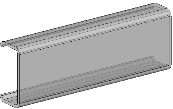
- Cold formed L profile (equal or unequal legs)
- Cold formed U profile (equal or unequal legs)
- C profile lipped
- V shaped profile
- Top Hat shape (Omega)
- Girt and purlin shapes : Z, Sigma, Sigma Plus, Sigma Sleeve, C Plus, C Sleeve
- Single Cleat and Double Cleat
For existing section tables this radius column will be added automatically but the values will be empty or 0.
There was also a new section table added called L Flex Angle Rounded for drawing angular profiles with a specified angle instead of always perpendicular like the standard angle shapes.
Tip Each section table has a property for automatically activating unfolding on all the profiles that are drawn with the section table
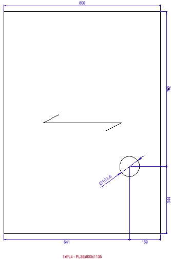 Add span symbol to regular plates
The span direction can be activated in the advanced properties of the plate.
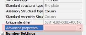
A span symbol can be activated for plates to indicate a certain direction on the workshop drawing. The span direction can be used to determine the load bearing direction of grating and floor panels, grain direction for wood, or the direction of fibers in fiber reinforced plastics.
This tool can also be used to influence the orientation of the coordinate system of a plate without adding the span symbol on the shop drawings.
The short leg of the plate's triangle (ECS) shows the span direction in 3D (or load bearing/grain/fibers direction).
The span direction tool has the following options :
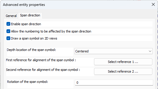
Allow the numbering to be affected by the span direction - When this is enabled, then the plate will receive a different part number from than plates if their span direction differs, even if the rest of their geometry is the same.
Draw a span symbol on 2D views - When this is activated the span symbol will also be shown on 2D views
Depth location of the span symbol - The available options are Centered, Top face or Bottom face. This depth is not visible on the plate in 3D but it does have an effect on the span symbol on the 2D view. The span symbol will be drawn on the specified depth of the plate. When the above setting Allow numbering to be affected... is enabled and the value is not centered then this setting will also affect the numbering sensitivity of the plate.
First/second reference for alignment of the span symbol - The reference geometry for the span symbol can be chosen, and additionally an angle.
When a second reference is chosen then the span symbol's alignment will be in between the 2 reference alignments that were chosen.
Only a geometry on the plate itself is allowed. See examples below.
Rotation of the span symbol - Here we can specify an angle witch which we can rotate the span symbol relative to the reference geometry(s).
Other new features
- During the Draw Section command a new option was added to the command line : or <Enter> to select an alignment geometry.
This allows the drafter to choose a (possibly sloped) alignment first before starting with the section creation tool  Some improvements were made to the Quick select : it is now possible to filter on all properties with a certain value and with a wildcard (*).
If you need to search all IPE shaped section then use the text IPE*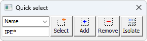
- A new bill and annotation property called PbColMarkGrid was added which contains the position of the assembly relative to the grid lines. It will display the 2 closest grid line names.
This new property is used in a small table that can be added as a secondary bill table on assembly sheets.
The new bill table filename is : \Pb_Lib\Workshop drawings\Bill Templates\Grid position per assembly.dwg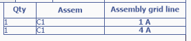
- The new reports Assemblies combined with bolt parts and Bolt parts were added to let you make use of the bolt and assembly part numbers.
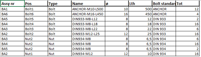
- New bills called Welders checklist, Bolt parts, and Assembly labels (stickers)
- Reports can have other reports automatically attached so that the combined report shows up as a single file. The columns are not required to match up
- Excel templates for reports can be more flexibly configured, for example to determine the cell formats and to determine where the columns get inserted.
- The export to step file feature now has the option to write a step file for each assembly in the drawing.
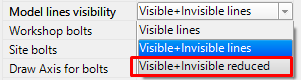
Previously it was only supported to write a step file for each part. For now this feature is only supported when the BricsCAD Communicator module is installed and licensed. - Views have an extra option in the visibility property :
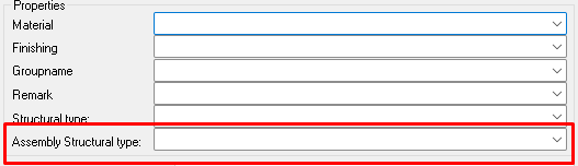
- It is now possible to directly choose the Assembly structural type when a new profile is being drawn :
- A new feature useful for bills called Fixed template strings.
These new strings allow you to configure the contents of a bill column. This offers a solution when you need to have a column contain custom contents such as project data or even multiple properties combined. Below an example template string where the project number and project name are configured as contents for fixed template column 1. In order to use this column in a bill all you need to do is activate the column PBColFixedTemplate1 in the bill.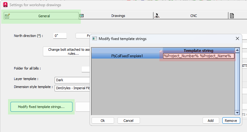
The links for navigating to the fixed template strings are highlighted in green - When bolts are set to shop (field) bolted, small parts are now automatically attached to (or detached from) the assembly of the larger part. Likewise when parts are joined into a single assembly, and there are bolts between those parts, they are automatically set to shop bolted.
- Shop bolts have better handling on drawings, reports, and drawing bills
- The macro dialog box for stairs and railings can now load and save
 the entire configuration of the values on the dialog box :
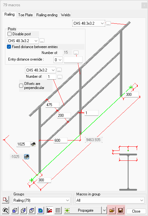
- The template text of a dimension now supports the additional "<>" characters to let Parabuild insert the measured value in that location of the text.
Before, only the %measure% word was supported, and only inside the Parabuild dimension template text.
The dimension template text can be modified with this command :
- Support for dimension text overrides in the AutoCAD/BricsCAD dimension property directly. The "<>" characters can be used to choose the location of the measurement value in the text. This dimension property will still be ignored if the Parabuild text template was set (see item above)
However do keep in mind that if the AutoCAD/BricsCAD measurement does not match with the actual measurement done by Parabuild, then the <> will be removed in the override.
This can happen with shortening or if the view has added scaling relative to the sheet.
Therefore Parabuild transfers such AutoCAD/BricsCAD override to the Parabuild dimension text template if the template is empty and the Parabuild measurement is not consistent with the AutoCAD/BricsCAD measurement.
From that point forward, the drafter should do further modifications in the text template and not the AutoCAD/BricsCAD override because only the Parabuild override will be persistent. - Support for the prefix and suffix property of AutoCAD/BricsCAD dimensions was added. When Parabuild overrides the dimension labels then it will take these prefix and suffix values into account. The prefix/suffix will be inserted before/after the measurement itself.
- A new sheet-level setting was added to remove the inch symbol in specified cases.
With this setting we can have the inch symbol removed from part/assembly sheets, while using the same dimension style on GA drawings, where you might want to keep the inch symbol. The new setting can be found in the Sheet properties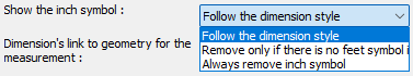
- To avoid unlinked dimensions becoming red and getting brackets, a new setting was added to allow the user to take control in that situation.
The new setting can be found in the Sheet properties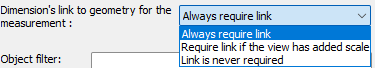
When this is set to no link required then the link between the 2D view and the 3D model is not required by Parabuild, meaning the dimensions's measured is left as-is.
The measurement is done on the 2D view whether that is correct or not and it becomes drafter responsibility to make sure the value is correct.
The default value is off (Always require link) because unlinked dimensions are risky. But it is less risky if you do not use added scale and no shortening.
The dimension value can be wrong when : - The view has an added scale (added scale compared to the sheet scale)
- The view is shortened
It is recommended to disable shortened views when you use this option.
It is very easy to create faulty dimension values with shortened views in combination with entities on 2D paper space like shown in this example : 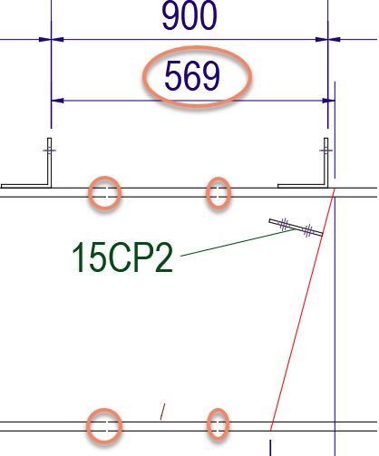
Warning Here is an example where the measurement 569 is wrong because dimension linking was disabled, and shortening was enabled on the view, and the freely drawn red line was used to measure to
- It is now possible to enable/disable stacked fractions in the dimension styles, the annotation styles, and all reports.
For the dimension styles we can choose per sheet which dimension style it should use. This allows us to set a different dimension style for GA sheets versus workshop sheets.
For annotations we can change the stacked fractions with this new setting :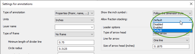
For the reports there is also the same stacking setting per property :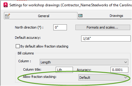
New annotation and bill properties
The following new properties/columns were added to the property list.
They can be used in Annotations and Bill of materials :
Name |
Description |
PbColSequence |
Erection sequence |
PbColNameOrMainName |
Name |
PbColNumber |
Position number for a part, assembly number for an assembly, bolt assembly number for a bolt, part number for a bolt part |
PbColGroup |
Extra property |
PbColObjectColor |
Object color |
PbColProductCode |
Product Code |
PbColAssemblyProductCode |
Assembly Product Code |
PbColFixedTemplate1 |
Fixed template 1 |
PbColFixedTemplate2 |
Fixed template 2 |
PbColFixedTemplate3 |
Fixed template 3 |
PbColFixedTemplate4 |
Fixed template 4 |
PbColFixedTemplate5 |
Fixed template 5 |
PbColFixedTemplate6 |
Fixed template 6 |
PbColFixedTemplate7 |
Fixed template 7 |
PbColFixedTemplate8 |
Fixed template 8 |
PbColFixedTemplate9 |
Fixed template 9 |
PbColFixedTemplate10 |
Fixed template 10 |
PbColByExcelTemplate |
Keep contents of the cell in the excel template |
PbColCostCategoryCode |
Category code |
PbColAssemblyCostCategoryCode |
Assembly Category code |
For assemblies only |
|
PbColMarkName |
Assembly name |
PbMarkDescription |
Assembly description |
PbColMarkTotalLength |
Total length of assembly |
PbColMarkTotalWidth |
Total width of assembly |
PbColMarkTotalHeight |
Total height of assembly |
PbColMarkGrid |
Assembly grid line |
PbColMarkMainName |
Name of main part |
PbColMarkMainPosNumber |
Main part number |
PbColMarkMainLength |
Length of main |
PbColMarkMainMaterial |
Material of main |
PbColMarkMainFinishing |
Finishing of main |
PbColMarkMainColor |
Color of main |
PbColMarkMainFabricator |
Fabricator of main |
PbColMarkMainRemark |
Remark of main |
PbColMarkStructuralDesc |
Assembly structural description |
For sheets only |
|
PbColSheetNumber |
Sheet number |
For views only |
|
PbBillColViewNumber |
View number |
For bolts only |
|
PbColBoltConnectedMarks |
Connected assemblies |
PbColBoltWasher1Standard |
Washer 1 |
PbColBoltWasher2Standard |
Washer 2 |
PbColBoltWashersStandard |
Filler washers |
PbColBoltNut1Standard |
Nut 1 |
PbColBoltNut2Standard |
Nut 2 |
PbColBoltWasher1PartName |
Washer 1 |
PbColBoltWasher2PartName |
Washer 2 |
PbColBoltWashersPartName |
Filler washers |
PbColBoltNut1PartName |
Nut 1 |
PbColBoltNut2PartName |
Nut 2 |
PbColNrOfBoltsInPattern |
Number of equal bolts in the same pattern |
PbColBoltNrOfNuts |
Number of nuts used by the bolt |
PbColBoltNrOfRegularWashers |
Number of regular washers used by the bolt |
PbColBoltNrOfFillerWashers |
Number of filler washers used by the bolt |
PbColBoltNrOfAllWashers |
Total number of washers used by the bolt : regular and filler washers combined |
PbColBoltAllPartNumbers |
All of the part numbers and their amount in use by the bolt assembly |
PbColBoltAssemblyNumber |
Bolt assembly number |
PbColBoltAllNumbers |
Number of all bolt parts |
For bills only |
|
PbColSectionBoundingBoxArea |
Area (m³) of bounding box of the section (also works on plates) |
PbColTotalLength : for the total length of all items on the row |
|
Extra properties, currently only available in annotations |
|
ViewNumber |
Number of the view |
CameraName |
Name of the camera (direct from camera or from view if there is a camera linked to the view) |
OtherSheetName |
Just like SheetName, but it only has a value when the callout camera refers to another sheet |
OtherSheetNumber |
Just like SheetNumber, but it only has a value when the callout camera refers to another sheet |
View relation to the Part/Camera/WCS |
|
ViewZAngleToEcsX |
Angle rotation (up to 180°) to the EcsX of the MainPart on part/assembly drawings, or CameraX for GA's. |
ViewZAngleToEcsY |
Angle rotation (up to 180°) to the EcsY of the MainPart on part/assembly drawings, or CameraY for GA's. |
ViewZAngleToEcsZ |
Angle rotation (up to 180°) to the EcsZ of the MainPart on part/assembly drawings, or CameraZ for GA's. |
ViewZAngleToWcsX |
Angle rotation (up to 180°) to the WcsX |
ViewZAngleToWcsY |
Angle rotation (up to 180°) to the WcsY |
ViewZAngleToWcsZ |
Angle rotation (up to 180°) to the WcsZ |