Bolts / Holes
These are all the commands for drawing and modifying bolts and holes:
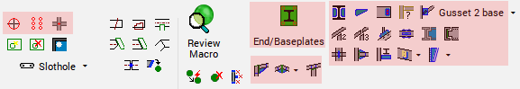
- Bolt Standards
- Draw Bolt
- Bolts on a Plane
- Bolts on Touching surfaces
- Galvanizing Holes
- Check for New Holes
- Remove Holes and Cuts
- Slotted Hole
- Hole <-> Threaded Hole
- Hole <-> Countersunk Hole
- Hole <-> Blind Hole
 We can choose to draw one of these other bolt types by choosing the bolt assembly name for the bolt.
In the default installation the rod and standalone nut assemblies rods are called Anchor rod, Rods, Rods single group, and Standalone nuts :
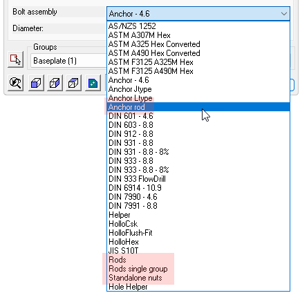
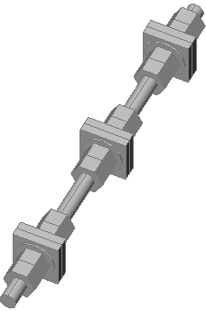
It is possible to draw simple and complex rods with the same Parabuild tools that are used for drawing bolts, nuts and washers.
A rod can tighten up to 3 groups of materials where a normal bolt can only tighten 1 group of material. A maximum of 4 parts can be activated on each side of the material for a total of 8 parts per tightening group. A group can also be a standalone combination of (square) washers and nuts such as for anchors embedded in concrete. In this scenario the group does not fasten any plates together.
In the rod assembly settings we can choose the type of part to be used in each position, and when drawing the actual rod we can activate or deactivate individual parts as needed.
Once the rod or standalone nut is drawn we can change the parts in the Advanced Parts configuration dialog.
This dialog is available from the Advanced button in the macro dialog or from the Advanced parts configuration property of the bolt.
In the center of this dialog we can enable or disable the parts around the tightening groups.
However it is not necessary for these groups to tighten something.
In the case of an embedded anchor rod we may want the rod to embed a square plate which can be activated as a square washer. In this scenario there is no need to draw additional plates in the model.
The square plate will be listed in the reports as a square washer as part of the anchor rod assembly, the name for the square washer can be adapted in the Bolt Parts Library.
When we are activating the parts of a tightening group that is not tightening anything then we can use the group offsets at the bottom of the dialog to position the tightening group.
The start offset is the offset measured from the start of the rod.
The end offset is the offset measured from the end of the rod.
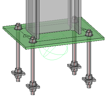
This is an example of an anchor rod with the last tightening group having a square washer and two nuts activated. The C Group Offset End was used to position the square washer and nuts relative to the ending of the rod.
Nuts and washers can now be drawn without a base bolt. We can still use the same bolt object for this which gives us all the advantages such as ease of drawing, automatic hole creation, and unified handling in reports and exports.
Standalone nuts could be solitary, or a combination of nuts and washers in case they are to be used with custom-created bent rods.
Configuring rods or standalone nuts
Rod and standalone nut assemblies can be configured in the Bolt Assemblies dialog.
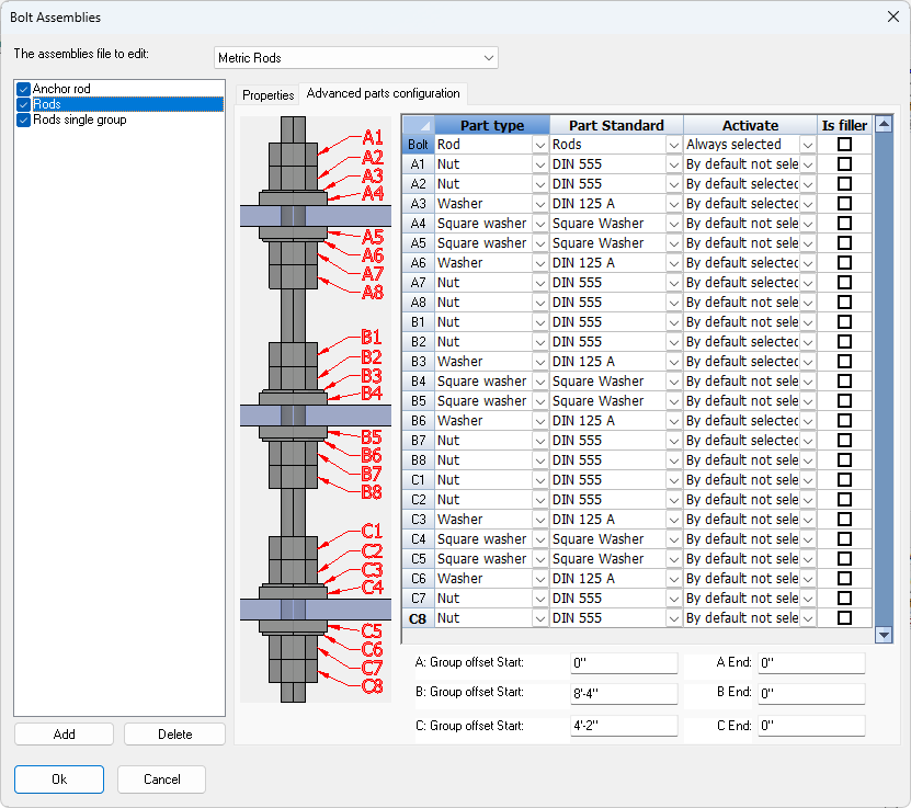
On the Advanced parts configuration tab it is possible to choose what part type should be used on each position, and whether each part should be activated by default or not the first time that a rod is drawn.
A condition for being able to add these part types is that the bolt part types already exist in the Bolt Parts Database.
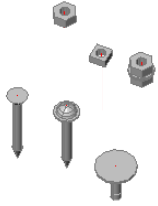
The following part types can be added to the Bolt Parts Database and can be used as part of a bolt assembly:
|
Example |
Description |
|
|
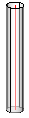
Rod |
|
|
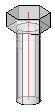
Hex head bolt |
|
|
Square head bolt |
|
|
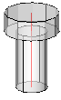
Cylinder head bolt |
|
|
Countersunk bolt |
|
|
Domed head bolt |
|
|
Rod type None |
|
|
Nut |
|
|
Square nut |
|
|
Washer |
|
|
Square washer |
|
|
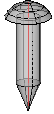
Sharp point length |