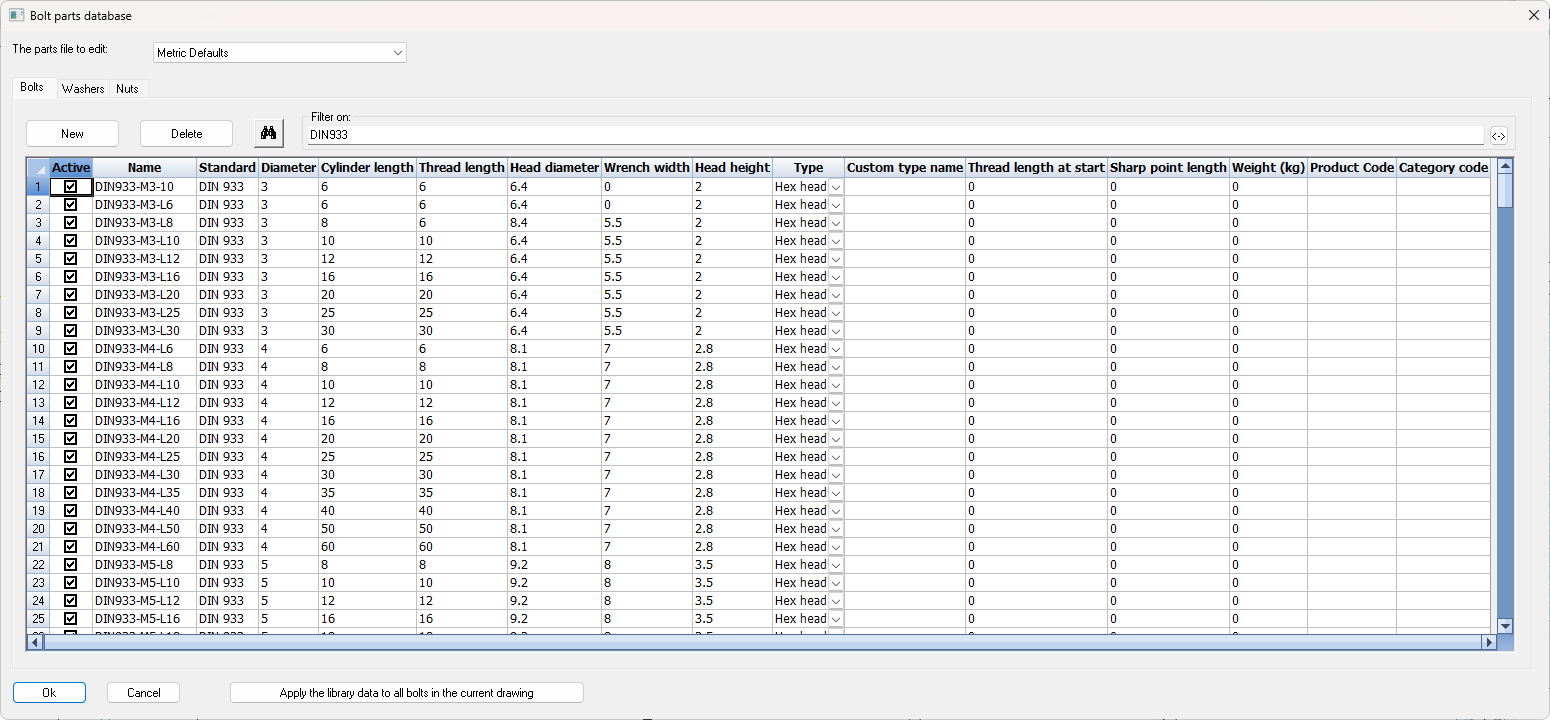
Bolt Parts database
The bolt parts dialog can be opened from the Parabuild Settings dialog.
All bolts, nuts and washers to be drawn come directly from this database.
This database contains every bolt, washer, and nut with its exact dimensions (diameter, length, thread length, ...).
This enables Parabuild to select a bolt from this list and will choose the shortest bolt length that is available in this list.
Every part has a checkbox in front of its name. If the box is not checked, Parabuild will never use the part. This allows parts to be turned off without having to delete them. This feature can prove very useful if a part with a certain diameter, length and standard is never used or is not in stock, in which case it can be turned off.
All parts in the available lengths and diameters for the respective standards have already been entered.
We will explain the options in the dialog in more detail:
The parts file to edit - The parts library is split up in several files as a way of grouping them based on metric or inches, rods, manufacturer, etc...
Filter on - Because the number of parts can total more than 1000, a filter can be applied. Type DIN933 in the edit box, and only the parts with DIN933 will be displayed. Click on the adjacent button and all except those with DIN933 will be displayed.
Apply the library data to all bolts in the current drawing - This action will check the current drawing file and will update all of the bolt parts with the bolt parts in the library. The bolt assembly names are used to find out the bolt parts so if the assembly name does not exist in the library then nothing will be done.
A use case for this audit is when your library has changed and you want to update the drawing or when you receive a drawing from another drafter who does not have your library and you want the drawing to be updated to use your library.
The columns for bolts
Active - Disabling the check box will disable the part. Parabuild will never use it in any bolt assembly.
Name - This is the part name that will be used in reports for this part. It also has to be unique across the parts file.
Standard - The standard can be used in reports but more importantly this text field is used in the Bolt Assemblies to let Parabuild select a part in a certain position of the bolt. Essentially this links bolt assemblies with bolt parts.
Diameter - This is the diameter of the cylinder of the bolt, ignoring any tread
Cylinder length - This is the length of the cylinder without counting the head height, even for countersunk-type bolts. In the 3D model and in reports, the head height of countersunk bolts is included in the bolt length to account for the common practice to include the countersunk head's length in the bolt length. Here in this dialog we're entering the cylinder length behind the countersunk head so take care to subtract the head height when entering bolt sizes from a countersunk bolt catalog. For normal bolts you should not subtract the head height from the catalog's length.
Tread length - This is the tread length of the bolt. The tread ending as well as the runout are drawn in 3D each as a circle. The tread is also used to determine the bolt length automatically based on the tread start rule that was chosen in the Bolt Assembly.
Head diameter - The overall diameter of the bolt head.
Wrench width - The wrench width. This can be ignored for countersunk bolts.
Head height - This is the height of the head for bolts with a head, but also the head depth of countersunk bolts.
Bolt type - These are all the supported bolt part types :
|
Example |
Description |
|
|
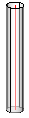
Rod |
|
|
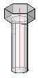
Hex head bolt |
|
|
Square head bolt |
|
|
Cylinder head bolt |
|
|
Countersunk bolt |
|
|
Domed head bolt |
|
|
Rod type None |


Custom type name - By default the reports will list the type name of the part as it is shown in the Type column. In some cases this type name is not descriptive enough when special types are added such as rivets, nails or screws. If this field is not empty then it will be used in the type name in reports instead of the Type column text.
Sharp point length - For representing screws, this can be used to sharpen the end of the bolt. The length is the distance over which the bolt's end should reduce from normal diameter to 0. The sharp point length does not add extra length to the bolt.

Product code - Enter the product code that should be used in reports for this part
Category code - Enter the category code that should be used in reports for this part
The columns for washers

Active - Disabling the check box will disable the part. Parabuild will never use it in any bolt assembly.
Name - This is the part name that will be used in reports for this part. It also has to be unique across the parts file.
Standard - The standard can be used in reports but more importantly this text field is used in the Bolt Assemblies to let Parabuild select a part in a certain position of the bolt. Essentially this links bolt assemblies with bolt parts.
Diameter - This is the diameter of the hole in the washer. This determines the diameter of the bolt with which this washer can be paired with. The Bolt Assembly's washer tolerance can be used to make it match up with unequal diameters (within the tolerance).
Type - Choose between regular washer and square washer. This option is not used when the complex bolt part is active.
|
Example |
Description |
|
|
Washer |
|
|
Square washer |

Custom type name - By default the reports will list the type name of the part as it is shown in the Type column. In some cases this type name is not descriptive enough when special types are added using the complex part such as bevel washers, nylon plugs, or hold down clips. If this field is not empty then it will be used in the type name in reports instead of the Type column text.
Outer diameter/width - This is the outer diameter or the width of the square washer. This option is not used when the complex bolt part is active.
Length - This is the thickness of the washer. When the complex bolt part is active this will be the functional thickness occupied by the part on the bolt's axis and it is in that case still important.
Product code - Enter the product code that should be used in reports for this part
Category code - Enter the category code that should be used in reports for this part
Complex bolt part - When enabled, this allows us to display complex geometry to represent bevel washers, cap nuts, nylon plugs, hold down clips, and any other parts that can be drawn with extrusions (+revolves).
There are several reasons for using complex bolt parts to draw special bolt parts instead of drawing them as regular parts or structures:
- Ease of use and automation during drafting : all commands and macros that can draw bolts allow us to draw these special parts instantly and in the right location, which is a big time saver.
- Reports generated by Parabuild will accurately list these parts as sub parts of the bolt assembly. If they would be drawn as separate parts then they would be listed as such in the reports.
- The resources required to draw these complex parts on the graphics card, CPU, and dwg file size are significantly reduced. Parabuild uses several optimizations to reduce the resource requirements compared to normal AutoCAD/BricsCAD objects. This is particularly important when thousands of these parts are drawn in the 3D model.
General notes about the bolt, bolt parts and their automatic positioning
The following items and terminology should be understood first in order to know how the complex bolt parts can be used.
- Bolt parts are positioned from the start of the bolt (the bolt head) and then down the axis. Parabuild automatically positions the bolt parts on the axis based on their size and also based on the material that is clamped by the bolt.
Consider this theoretical example to understand how positioning of the part on the bolt is decided :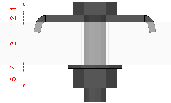
Dimension 1 is the bolt head's thickness. This could be 0 for example for rods.
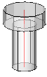
Dimension 2 is the thickness of the first washer. This thickness is defined in the Length column of the washer. This space is reserved for the washer even though the washer itself can be larger than this like in this hold down clip example.
Dimension 3 is the clamped material. This size could be different each time and is decided during the drafting process. This material thickness decides the position of the next bolt part.
Dimension 4 is the thickness of the second washer, which is also defined in the Length column of the washer.
Dimension 5 is the thickness of the first nut, which is defined in the Length column of the nut.
It is important to understand this linear process starting from the bolt head moving along the bolt shaft one after the other while moving along the shaft of the bolt.
When the last bolt part's position is decided, Parabuild can finally decide the bolt or rod length based on the Bolt's length properties such as added length and also the available bolt lengths for the specified diameter and type in the bolt parts database.
- The functional thickness of the part is not defined in the complex bolt part dialog but in the main bolt parts dialog in the column Length of the washer or nut. The functional thickness is the thickness that will determine the location of the next material (next bolt part or clamped material such as grating, whichever comes first). It should be the offset between the lower end of the bolt head, and the start of the next material.
In these examples you can see that this might not be the complete part :
In these examples the functional thickness of the black complex washers are indicated in red.
The bolt uses this thickness to decide the starting position of the clamped material (grating in this case) behind this part - There is a different setting called Thickness for next bolt part in the complex bolt part dialog which is not to be confused with the functional thickness :
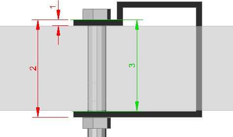
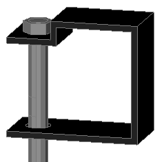
This is an example of a clip (black) that clamps a grating panel and other material(s), shown here in grey.
This example highlights the Functional thickness with dimension 1 and the Thickness for next bolt part with dimension 2 to highlight the differences between them.
In essence, the Functional thickness tells where the next material may start, either bolt part or fastened material. The Thickness for next bolt part tells where the next bolt part may start, essentially overriding Parabuild's automatic position calculation with a custom value for special bolt parts that extend beyond the fastened material.
If we were to let Parabuild calculate the default part offset, then it would use the distance as displayed with dimension 3. That would be correct in most cases but not this type of clip that surrounds the entire grating panel and the material it is fastening the grating panel to.
The options for complex bolt parts are are as follows :
Enable as a complex bolt part - When you enable this, the extrusions in this dialog will be used to represent the part
Location of this part - The following options are available :
- Somewhere on the bolt shaft - This will position the part somewhere between the bolt head and plate material or between a nut and plate material. This option should be used for washers, hold down clips, and other special cases.
- At the start of the bolt - This will position the part at the start of the bolt (eg capped nuts).
- At the end of the bolt - This will position the part at the end of the bolt (eg capped nuts, plugs, anchor bolt sleeves).
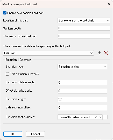
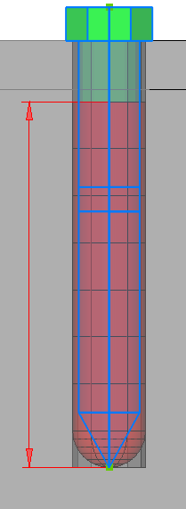
Sunken depth - This depth is used for a special case where a bolt part needs to sink the bolt head inside the material, which is typical in grating :
The sunken depth is indicated with the red dimension for this hold down clip example that requires it.
The fastened material (grating) and an indicative field hole are shown in blue. The grating bars are not displayed for clarity in this example.
Correct positioning of the bolts between grating bars is not automatic and should be done either by the drafter or field located. For the purpose of bolts & holes, a grating panel is considered a regular thick plate. This is also reflected by the full-size (field) holes that Parabuild draws in grating panels. The provided sunken depth for the clip works around this limitation by forcing the bolt head lower than the start of the clamped material.
Thickness for next bolt part - This setting will make sure that the nuts and washers are drawn after the material of the clip. The material size of the complex bolt part is not detected automatically for various reasons so we have to enter the size here if necessary.
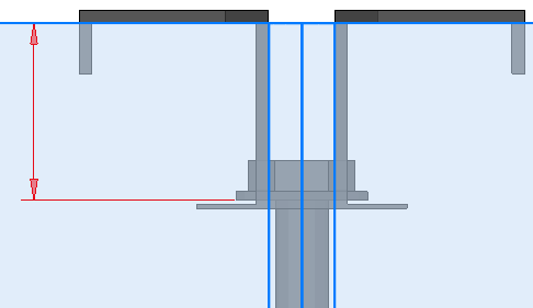
You only need to fill in this value when the next bolt part needs to be drawn much farther away than defined by the functional thickness like in this case :
This is an example of a clip (black) that clamps a grating panel (grey).
This example highlights the Functional thickness with dimension 1 and the Thickness for next bolt part with dimension 2 to highlight the differences between them.
In essence, the Functional thickness tells where the next material may start, either bolt part or fastened material. The Thickness for next bolt part tells where the next bolt part may start, essentially overriding Parabuild's automatic position calculation with a custom value for special bolt parts that extend beyond the fastened material.
If we were to let Parabuild calculate the a default part offset, then it would use the distance as displayed with dimension 3. That would be correct in most cases but not this type of clip that surrounds the entire grating panel and the material it is fastening the grating panel to.
The extrusions that define the geometry - Several extrusions can be combined to visualize the part. Use the + and - button to add extrusions and use the combo box to see and modify all of the extrusions.
Extrusion type - Each extrusion type is explained with an example :
|
Type |
Example 2D section |
Example 3D result |
Description |
|
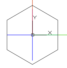
Revolve around hole |
|
|
The result of the revolve is shown in black. |
|
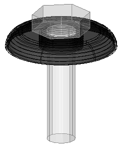
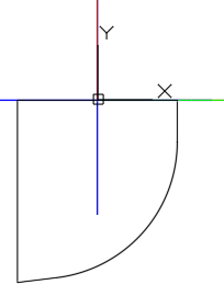
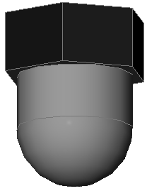
Revolve around poly ends |
|
|
The result of the revolve is shown in black in this domed nut example. |
|
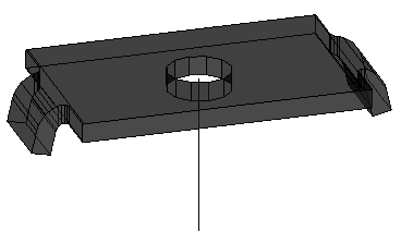
Extrusion to side |
|
|
The result of the extrusion is shown in black for this hold down clip. |
|
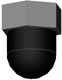
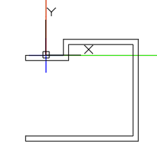
Extrusion parallel to bolt axis |
|
|
The result of the extrusion is shown in black in this domed nut example. |

This extrusion subtracts - Use this option to subtract the other extrusions of this bolt part.
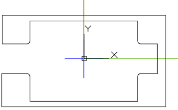
This example hold down clip was achieved by first adding this section with the Extrude to side option : 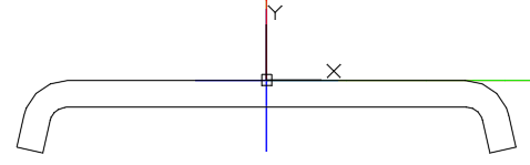
And then subtracting this section with the Extrude to side option (a single section for efficiency) :
Extrusion rotation angle - This is the rotation angle for the extrusion around the bolt axis.
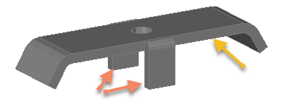
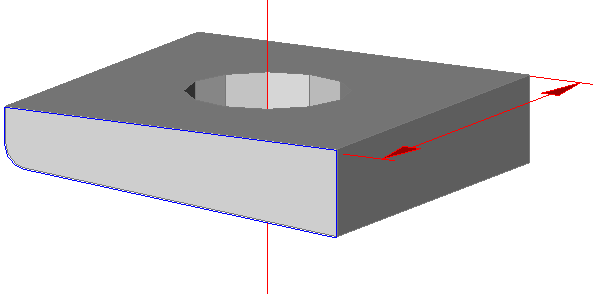
This is an example case where the extrusion for the extra flanges are rotated 90° to achieve the desired result.
The normal extrusion is indicated with a yellow arrow, the 90° rotated extrusion is indicated with orange arrows.
Offset along bolt axis - This option can be used in cases where the extrusion needs to be moved from its normal position as defined in the section drawing. It is notably useful in cases where the part does not need to come before or after the holes.
This example of a plug uses this setting.
The plug itself is drawn as a revolve around the axis :
|
|
|
|
Example use case of Offset along bolt axis set to minus the plug's length |
How this same plug would be displayed with the Offset along bolt axis set to 0 |
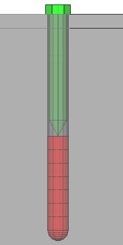
In red we can see the plug, in green/blue we see the bolt shaft, and in black/grey we can see the material and holes.
Note that the hole in the 2nd material is a limited depth hole.
Normally the plug would be drawn with it's top at the bottom of the blind hole which is the starting position for washer 2.
The offset is set to the minus length of the plug so that the bottom of the plug touches the end of the blind hole.
Extrusion length - This option is required for linear extrusions. It specifies the depth of the extrusion :
The red dimension represents the extrusion depth in this bevel washer example that uses the Extrusion to side type. The blue circumference is the extrusion's 2D section.
Side extrusion offset -This is an offset perpendicular to the bolt axis and the 2D section (parallel to the extrusion length).
This is a theoretical example of an off-center washer to demonstrate this offset :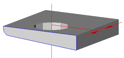
The red dimension represents the side extrusion offset in this washer example that uses the Extrusion to side type. The blue circumference is the extrusion's 2D section.
Extrusion section name - Choose the 2D section that should be used for the extrusion. You can use a Custom section shape that was drawn specifically for the part, or you can use a section from a section table.
It would be recommended to store all the custom section shapes for bolt parts in this folder : \Pb_Lib\User Sections\Bolt parts\
This will make sure that these sections are not intermixed with custom section shapes that are used to draw profiles.
All the section tables for bolt parts are gathered under the Bolt parts groupname and are hidden when placing members.
This action button will still show all hidden tables so you will see many more section tables than when you would draw a new profile.
The reason is not to clutter the profile selection dialog with bolt part sections when it is used for drafting commands in Parabuild.
Note
It is not necessary to create an extrusion that subtracts the hole of the part. Parabuild will subtract the hole automatically when needed using the diameter specified in the diameter column
The columns for nuts

Active - Disabling the check box will disable the part. Parabuild will never use it in any bolt assembly.
Name - This is the part name that will be used in reports for this part. It also has to be unique across the parts file.
Standard - The standard can be used in reports but more importantly this text field is used in the Bolt Assemblies to let Parabuild select a part in a certain position of the bolt. Essentially this links bolt assemblies with bolt parts.
Diameter - This is the diameter of the hole in the nut, ignoring any tread. This is the diameter of the bolt with which this nut can be paired with.
Type - Choose between regular nut and square nut. This option is not used when the complex bolt part is active.
|
Example |
Description |
|
|
Nut |
|
|
Square nut |


Custom type name - By default the reports will list the type name of the part as it is shown in the Type column. In some cases this type name is not descriptive enough when special types are added using the complex part such as domed nuts. If this field is not empty then it will be used in the type name in reports instead of the Type column text.
Outer diameter - This is the total diameter of the nut. This value can be ignored for square nuts. This option is not used when the complex bolt part is active.
Length - This is the total length of the nut. When the complex bolt part is active this will be the functional thickness occupied by the part on the bolt's axis and it is in that case still important.
Wrench width - This is the wrench width for a regular nut, or the width of a square nut. This option is not used when the complex bolt part is active.
Complex bolt type - This is explained already above for washers. It works exactly the same for displaying a complex geometry for nuts.
Product code - Enter the product code that should be used in reports for this part
Category code - Enter the category code that should be used in reports for this part