Global settings
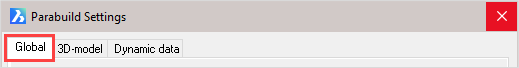
The global settings are divided into the following categories:
- Drawing parabuild elements
- Languages
- Standard tolerances for cutting
- Distances
- Standards of the position numbers of plates
- Standards of the position numbers of members
- Standards of the position numbers of structures
- Standards of assembly numbers
- Global settings
- Standard values for newly drawn members and plates
- General plate settings
The buttons at the bottom of the dialog are referenced here:
- Library Localization
- Bolt Parts database
- Bolt Assemblies
- Variables of Macros
- Material / Finishing
- Threaded Holes
- DSTV WeldPoints
- Clash Control
- Object Filters
- Structural types
- CNC contour settings
- Modify K-Factor tables - This button allows modification and creation of new K-factor tables for unfolding of parts. It is explained here.
Drawing Parabuild Elements
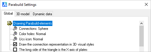
Show macro spheres: This is a switch, which when checked it will show the macro spheres when the 2D visual style is active. When unchecked all spheres will be hidden in the 2D visual style.
Color Holes: Hole color - The options are Normal / Red
UCS icon: This refers to the Element Coordinates System (ECS) of plates and profiles. The options are :
- Normal, which draws a triangle at the origin of the part
- Detail, which draws a UCS icon at the origin of the part
Draw the connection representation in 3D visual styles: This is a switch, which when checked will show the macro spheres when one of the 3D visual styles are active. When unchecked all spheres will be hidden in all the 3D visual styles.
The long side of the triangle is the X axis of the plates: The origin triangle direction may be switched from the Y axis (checkbox Unchecked) to the X axis (Checked). This option will only come into effect when the UCS icon is set to Normal
Languages
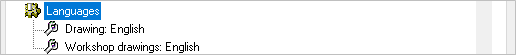
The language option for Drawing refers to the language of the user interface in Parabuild. That means all the dialog boxes, command line prompts and toolbars.
The language option for Workshop drawings refers to the language of the automatically generated workshop drawings and GA drawings only. More specifically the title block and Bill of Material on these drawings.
The available languages include:
- English
- Dutch
- French
- German
- Korean
- Traditional Chinese
Distances
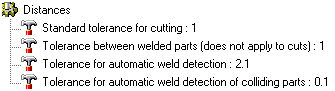
Standard tolerance for cutting: Commands for adding cuts to parts will follow this default value. Default value = 1 mm.
Tolerance between welded parts (does not apply to cuts): The distance (gap) that should be generally applied between welded parts.
This applies to all welded parts except in case a cut is touching one of the parts. In case of a cut, the above tolerance counts.
Tolerance for automatic weld detection: This tolerance is used by the Workshop Drawings generation command, and by the DSTV and DXF export commands.
When parts are not touching but within this tolerance, then Parabuild will assume that the parts are touching and need to be welded. The touching status will determine whether the welded part will get certain dimension on the shop drawing or CNC contours or matchlines in the CNC files.
Tolerance for automatic weld detection of colliding parts: This tolerance is used by the Workshop Drawings generation command, and by the DSTV and DXF export commands.
When parts are not touching but colliding with each other but within this tolerance, then Parabuild will assume that the parts are touching and need to be welded. The touching status will determine whether the welded part will get certain dimension on the shop drawing or CNC contours or matchlines in the CNC files.
General numbering settings

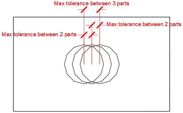
Rounding of holes for numbering: This is the tolerance that Parabuild should use when searching for identical parts and assigning numbers to them.
In practice, Parabuild will assume half of this tolerance when comparing 2 parts. This means that the total maximum difference between 3 parts will be the full tolerance.
The below illustration shows the difference between the tolerance of 2 parts and the total tolerance of 3 parts or more.
It shows 3 plates on top of each other, but with slightly offset hole positions.
Rounding of plates for numbering: Same as above, but this refers to the tolerance of plate edges for number assignment.
Rounding of members for numbering: Same as above, but this refers to the tolerance of member edges and cuts for number assignment.
Standard parts relative path: This value should point to a folder inside the Parabuild library (the full path is by default c:\Parabuild\Pb_Lib\StandardPartsLib\Metric\ or \Imperial\).
The purpose of this tool is to assign predetermined part numbers to "off the shelf" parts so that those parts can simply be taken out of storage instead of produced.
For more information about this tool see the Standard Parts Library topic.
Check welded part contours while numbering parts - This option is explained in detail in the Check contours when numbering parts topic.
Take the assembly Center of Gravity into account when numbering - When this option is enabled, then main parts with different COG locations will receive different part numbers.
If this is disabled then 2 main parts could get the same part number even if they have different COG locations (when they are used in different assemblies). In that case, the Dstv output will still write a different file for each part but with the assembly number added to the cnc filename. Enabling this option will prevent this situation from occurring and can result in shorter cnc files.
Note that the cnc files produced will always be correct no matter how this setting is set.
Use part number as assembly number for all single part assemblies - When this is enabled and an assembly is comprised of just 1 part, then that part's number will be used for the assembly number
Defaults for numbering
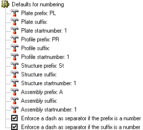
Plate prefix: This is the prefix given to plate numbers i.e. PL 1 - this may be edited to suit
Plate suffix: This is the suffix given to plate numbers i.e. PL 1 01 - this is optional
Plate startnumber: This is the first number given to the plate i.e. PL500. This number will be automatically incremented if the given start number is already occupied.
The above 3 settings work in exactly the same way for profiles, structures and assemblies
Enforce a dash as separator if the prefix/suffix is a number - When this option is enabled and the prefix is 4 and the number is 3, the resulting number will be 4-3. When the option is disabled the resulting number would be 43
Global Settings
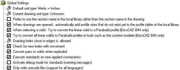
Default unit type: Use None if you want to work in both Metric and Imperial projects. Choosing Metric will cause Parabuild to assume Metric in drawings with conflicting units variables. The same applies to the Inches option. Options = None / Metric / Inches
Current drawing unit type: Change this option only when Parabuild has assumed the wrong units for the current 3D drawing. Options = None / Metric / Inches
The following variables are used by Parabuild to conclude whether a dwg file is Metric or Imperial :
|
Variable name |
Variable value |
|
Measurement |
0 for Imperial 1 for Metric |
|
LUnits |
2 for decimal metric 3 or higher for imperial |
|
InsUnits |
1 for Imperial 4 for millimeters |
The setting Current drawing unit type in this dialog box will be set to what could be derived from these 3 variables. You can change the setting in this dialog to correct it if needed.
AutoCAD and BricsCAD also have the following variables that may interest you especially when working with Imperial units:
|
Variable name |
Variable value |
|
Dimzin |
Controls the suppression of zeros in the primary unit value in dimensions. 0-7 for Imperial 8 for Metric |
|
Dimtzin |
Controls the suppression of zeros in tolerance values in dimensions. 0-3 for Imperial 4, 8 and 12 for Metric |
|
DimFrac |
Sets the fraction format when DIMLUNIT is set to 4 (Architectural) or 5 (Fractional). 0 : Horizontal stacking 1 : Diagonal stacking 2 : Not stacked (for example : 1/2) |
|
DIMTFac |
Scale factor for fractions |
|
DimLUnit |
Sets units for all dimension types except Angular. 1 : Scientific |
|
DimPost |
Specifies a text prefix or suffix (or both) to the dimension measurement. |
|
luprec |
Sets the display precision for linear units and coordinates. |
|
unitmode |
Controls the display format for units. 0 : Displays fractional, feet-and-inches, and surveyor's angles in "report" format using spaces as delimiters 1 : Displays fractional, feet-and-inches, and surveyor's angles in "input" format without including spaces and, in some cases, substituting dashes for spaces |
|
InsunitsDefSource / InsUnitsDefTarget |
These are only used when the source or target drawings of an insert operation don't have the InsUnits variable set |
Prefer to use section name in the local library rather than the section name in the drawing - When this is enabled then Parabuild will not use the naming of parts as they are stored in the dwg file, but will rather use the names that it can find in the local section library.
It is an important choice to make because this can influence the profile names used when shop drawings and reports are generated.
When the person who created the original file is using Parabuild in a different language, then this setting can make it keep the original drafter's name (default), or it can make the section names change for many profiles.
Besides different languages of Parabuild a name change can also be triggered by differently configured section tables in the library.
When drawings are opened : automatically add profile sizes that do not exist yet to the profiles tables in the local library - When enabled, the existing section tables in your \Pb_Lib\Prof\ folder will grow automatically with the section sizes used in the opened files. Not only that, but this will also re-create the section tables that the original drafter used. The section tables will only grow with the sections used. This will not fully restore the entire section table that the original drafter had because that information is not in the drawing. The drawing contains all section creation data per profile in the drawing.
When selecting a solid : try to convert the linear solids to profiles (BricsCAD BIM only) - When you select a solid during any Connection command then Parabuild will attempt to convert this solid into a Parabuild profile. This tool relies on BricsCAD's Bimify command. The procedure to make this works is explained in the Various commands without icons topic.
Try to convert all linear solids to Parabuild profiles in tools such as the context modeler - This is the same as the above setting, but instead all linear solids will be converted to profiles the moment that the context modeler is opened.
Drawing holes close to an edge: Options = Not allowed / Allowed
The minimum distance between a bolt and the edge of a beam or plate can be set in the Clash Control dialog, but that will determine whether the color of the bolt will become yellow as a warning. It has no influence on the current option which can allow drawing holes very close to the edge.
Check for new holes with movement: Options = Off / On
(When a bolt is moved, the corresponding holes are moved with it. You can switch this off)
Convert parts to solids when exploded - When this is enabled then any Parabuild part that is exploded with the AutoCAD/BricsCAD command will be converted to an exact geometric copy of the part but as a 3D Solid. The Parabuild part itself will be removed.
This follows the logic of the explode command, which is essentially 'remove the top layer of intelligence of the part'.
When this is disabled then the explode command does nothing on Parabuild parts.
Execute standards on new applied connections: Options = On / Off (Refer to Standards for Connections)
Activate debug mode for standards (Warning messages): Options - On / Off
Only write Unicode files (Support for all languages): Options - On / Off
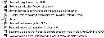
Standard weight for output: This value is the default weight that Parabuild should assume for objects that have no material assigned. The default value is set at 8000 kg/m³ - which is the approximate value for 1m3 of steel (7860 kg/m³).
Allow automatic classification of objects - When this is enabled, Parabuild will automatically assign Structural types to the objects whenever the drawing is being numbered.
Allow properties to be changed during automatic classification - This only works when automatic classification is also enabled. When this is enabled then the properties that are defined in the structural types are set to that entity. A default setting that is using these settings is column assemblies getting the C prefix for assembly, Beams getting the B prefix, bracing getting R prefix, etc.
K-factor table to be used when parts are unfolded - The table allows you to assign K-factors based on material, part name, plate thickness, bend radius, and bend angle.
During the unfolding process, this table will only be consulted if the K-factor was not found in the part's advanced properties, nor in the K-Factor and BendRadius columns of the section table, nor in the more options dialog of the section table.
At the bottom of this dialog you can also find the Modify K-factor tables button which allows you to modify or create a new K-factor table.
Phase: Sets the phase that all newly drawn objects should receive.
Standard bolt assembly: The default bolt assembly that connections and bolt tools should use by default. (See Bolt Assemblies)
Standard anchor bolt assembly: The default bolt assembly that anchor plate macros should use by default. (See Bolt Assemblies)
Save proxy data so that Parabuild objects become visible in plain AutoCAD/BricsCAD: This option allows the 'Proxy' details of a 3D-drawing to be saved.
Parabuild creates its own objects (profiles, plates, bolts ...) which means that without Parabuild, AutoCAD will not recognize these objects and therefore will not display the profiles. This is solved by the 'proxy' details, details on the appearance of the objects, which is saved within the drawing. One disadvantage of this is that the drawing becomes 2 to 3 times larger. However, this does not result in any great delay when opening or editing the drawing, as these details are not actively used, and is therefore not loaded into memory when working with Parabuild. Remember that when this option is turned on within an existing drawing and then saved normally, the details are not yet saved. This can be solved by either setting the variable 'ISAVEPERCENT' to 0, or by saving the drawing under another name.
One final requirement is that the proxy details on the computer without Parabuild is set to display. This can be set up in AutoCAD as follows: Tools > Options > Open And Save > Proxy Images for custom objects should be set to Show proxy graphics.
Save extra proxy data for rendering Parabuild objects in plain AutoCAD/BricsCAD: this is a sub-set of the previous option.
This will add additional proxy data for rendering of faces with 3D objects. Note that this option will not work independently as the edges are still needed to determine the faces. Therefore, both check boxes must be active if you want the rendering data to be written to file.
Standard values for newly drawn beams and plates
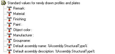
Remark: Here you may enter a standard Remark for newly drawn parts
Material: Here you may enter a standard material for newly drawn parts
Finishing: Here you may enter a standard Finishing for newly drawn parts
Paint : You can enter a free paint color text here, for indicating to the shop that the part needs to be painted
Object color: This property refers to the inherent color of the object. Contrary to the paint color this property does not necessary call for an action in the shop. This would be used for example when drawing parts in FRP Material which comes in various colors.
Manufacturer: Here you may enter a nominated Manufacturer for newly drawn parts
Group name: This property is not actively used by Parabuild, so it can be considered a free to be used "User property".
Default assembly name/description - This can be used to give an assembly a name. The default is to combine the assembly structural type with the main part name.
These properties can be a template string combining any number of properties, such as the structural type, material, main part name, etc...
This property can also be automatically assigned using template drawings or by structural type classification.
When the property was not individually set in the properties of the part then the default template string is used for that assembly. This default can be determined by the user in this dialog box.
When neither the assembly property or drawing default was set, the name of the main part is used instead.
The names PbColMarkName and PbMarkDescription can be used in bills and annotations to display the value of this property.
The name value will also be shown when the property PbColName is used in a bill or annotation.
General plate settings
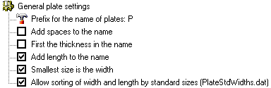
Prefix for the name of plates: The default value is PL - this may be changed to suit preference (i.e. PL8x100)
Add spaces to the name: Will add spaces between the characters (i.e. PL 8 x 100)
First the thickness in the name: Will place the plate thickness before the plate size (PL8x100 vs PL100x8)
Add length to the name: Will add the plate length to the plate name (i.e. PL8x100x190)
Smallest size is the width: Will assume the smallest size is the plate width (i.e. PL8x135x200 vs PL8x200x135)
Allow sorting of width and length by standard sizes (PlateStdWidths.dat): If enabled, Parabuild will use this file to determine what the standard plate widths are : c:\Parabuild\Pb_Lib\PlateStdWidths.dat.
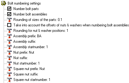
Bolt numbering settings
Parabuild can automatically number bolt assemblies and their individual parts: base bolt, nuts and washers.
Different prefixes and start numbers can be chosen for assemblies and each bolt part type. If enabled, bolt numbering will automatically run during the existing numbering commands.
Numbered bolt assemblies and parts can be used in annotations and bill columns, and can be useful on shop drawings (for shop bolts), GA drawings (field bolts), for shipping and on-site use for easy labeling and identification.
At the end of the settings dialog most of the bolt numbering settings are shown.
The following settings were added :
Number bolt parts - When this is activated all the bolt parts will receive a part number. A bolt part is for example a base bolt, a nut or a washer
Number bolt assemblies - When this is activated all the bolt assemblies will receive an assembly number. A bolt assembly is a bolt together with all of it's washers and nuts as it is drawn in the 3D model. If 2 bolt assemblies have a nut of a different standard or a different amount of nuts then they will get a different assembly number
Rounding of sizes of the parts - The rounding that should be applied when 2 bolt parts are compared to check if they should get the same bolt part number
Take into account the offsets of nuts & washers when numbering bolt assemblies - When this is enabled then not just the bolt parts are used to check whether assemblies are equal, but also the position of the bolt parts on the shaft of the bolt
Rounding for nut & washer positions - When the above option is activated, then this setting will be the rounding that should be applied when the offsets of 2 bolt assemblies are compared
The below 3 settings are repeated per assembly and each bolt part. We will explain them just once because they all have the same purpose but for different parts.
A bolt part or assembly number is comprised of 3 parts : the prefix, the number and the suffix.
For example :
BA 4 X
prefix xx xx - Specifies the prefix before the number
xx startnumber xx - Specifies the start number for the number. If the number is occupied the next available number will be used.
xx xx suffix - Specifies the suffix after the number