DSTV WeldPoints (weld markings)
DSTV weld points are points that are inserted in the automatically produced DSTV NC-files.
A point indicates on which spot an element must be welded on the profile. Because the CNC-machine can drill these points automatically, it can result in gaining time because one has to measure less when welding.
The points will normally be made by the machine with the tip of the (currently present) drill.
Because of the flexibility of the numbering of profiles and plates the program must place the points automatically. With some general options you can influence the placement of the point for each element.
The weld points discussed in this topic are old and there are now better tools to add these drill markings automatically. Therefore we recommend to use the newer CNC contour and matchline settings instead, even if you only need markings with the drill tip. The new CNC contours allow this too, and they are to be set up once and then forget. The older weld points require you to choose the weld point manually per part in the properties.
To use these older weld points we need to take the following steps :
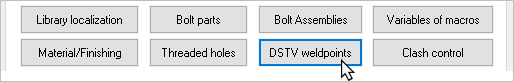
- Activate a weld points group in the DSTV weld point groups dialog shown below. We can access this dialog from the Global settings
- For each welded part that needs to receive a weld point in the Dstv file, choose the weld point name in the Properties panel of the profile or plate
- In the DSTV NC Settings you should still activate these weld points so that they are written in the Dstv file
When the weld points are set up correctly, then you will see crosses on the mark (assembly) drawings. These are the weld points that will be passed on to the machine. The crosses can be added to the assembly drawing for the convenience of the welder. This way one can see more easily on which spot the welded element and the weld point must match.
Assembly drawings and DSTV files will also get different names. Normally you have one DSTV file for each position number, but that is no longer possible when that profile has weld points. In that case the file name of the assembly drawing and the DSTV file will contain both the mark number and the position number. The result is more files and drawings, but it is an inevitable disadvantage.
The following dialog allows us to change the active group and to edit the points inside each group :
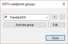
Creating a points list
Here you have to set one group as current in order for the DSTV weld points to work. The points in the current group will be used for this drawing (the current group can be established separately for each drawing).
The purpose of several groups is that one can create a different set of weld points for a certain project, and thereby can keep the normal weld points intact.
Modifying or adding points
When you click on Edit…, the edit DSTV points dialog box will appear :
Edit DSTV points
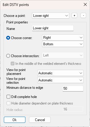
At the top of the dialog you see all points in the group. You can create new points or remove points with the buttons next to the list.
If you select a point from the list then the options for that point will be visible beneath it and you can modify these.
The settings for the weld point are explained below.
Name: The name for the point. We will later use this name if we want to use this point for a welded element.
Choose corner: You choose the corner where the weld point should be positioned on the welded element. The following illustrate all possible choices with an example:
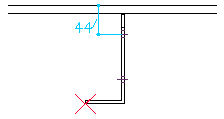
Corner left under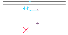
Corner left above - The point will only be placed where there is material, in this case below but the upper part of the angle bracket.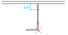
Corner right under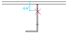
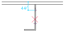
Corner right above - The point was not placed entirely at the top because the drill head cannot come this close to the flange. This clearance space is adjustable, see further in the manual.
Choose intersection: To understand this option we must imagine that a line is drawn through the welded element (on the weld plane). The weld point is placed on the first point where the line intersects the welded element. With this option you choose where this intersection line should be placed.
The following illustrate all possible choices with an example:
Intersection left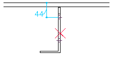
Intersection Right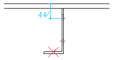
Intersection Above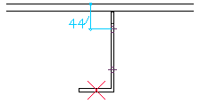
Intersection under + middle - With this example not only the option Intersection under was enabled but also the option In the middle of the welded element's thickness - The result is that the point will be placed in the middle of the bracket's thickness.
In the middle of the welded element's thickness: If this is activated then the point will be placed in the middle of the thickness at the local intersection.
Choose view: If this is set to Automatic then the software will always use the view that directly looks at the welding plane. However you can choose to manually set another view, in those cases where the automatic view is not desired (for example for brackets that are welded against the flanges of an I profile).
Minimum distance to edge: The machine can't move its drill too close to obstacles. If there is a point on the web of an I profile, then the weld point should keep clear a distance from the flange. Otherwise the drill would collide against the flange and CNC machine refuses to create the point.
The value you enter here is the clearance Parabuild will use automatically to avoid these occurrences.
Drill complete hole: If you activate this option, a complete hole will then be drilled instead of a point. This hole will never be visible in the 3D drawing. It will still be treated as if it is a weld point. Only during the communication with the CNC-machine a complete hole will be passed on instead of a point.
This hole can be useful, for example for stiffeners: we only have to drill one hole for both stiffeners and the hole is also more visible while welding.
Hole diameter dependent on plate thickness: If you activate this, you do not have to enter a diameter for the hole, but how much larger than the thickness the hole has to be (offset).