View Callouts and cameras inside views
 Callouts, cameras inside views, sheet and view numbers
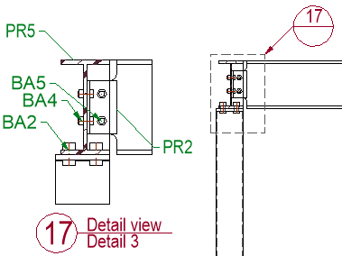
A view callout is an annotation on a section or detail camera that displays view number and sheet number (and optionally additional information). It tells the person who reads the drawing where to find the view that is referenced there.
To make this annotation possible a view can contain cameras that may be printed or not printed.
Each view and each sheet get a number and a name so that the annotation can display these numbers.
The camera inside the view is linked to a camera in model space, which in turn is linked to all of its views. This is how the annotation can show the view and sheet numbers that are being referenced.
We will explore each of these different steps in the process hereafter :
 Cameras inside views
Cameras on the model can be automatically inserted into main views during creation, or they can be pulled in while editing the view.
Which cameras are automatically added to a view is determined by this settings in the output settings :
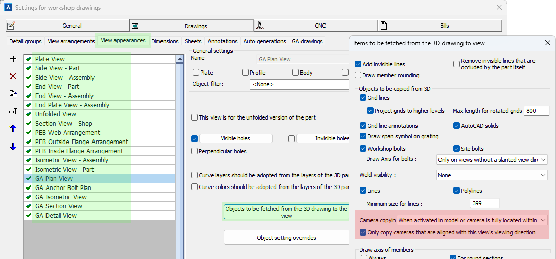
The links for getting to the location of the camera copying are highlighted in green
For existing views it is possible to add more cameras to the view with the manage cameras command :
Manage cameras inside view command
Command name : PrB_ManageCamerasWithinView
 This command is also accessible by double-clicking on a view, which will directly open the same manage cameras dialog box :
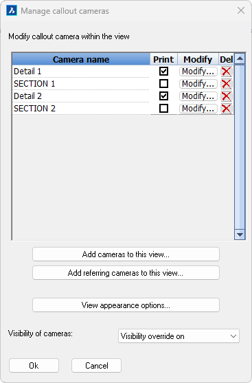
The purpose of all the items on the dialog are explained hereafter :
At the top we can see a list of all the cameras that are contained within the view.
Next to each camera name we can perform the following actions on the camera :
- Print camera - Enable this option if you want the camera to be visible when the sheet is printed.
- Modify camera - This button brings up the camera modification dialog of which the most important options are :
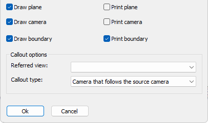
- Draw plane/camera/boundary - Enable the geometries of the camera that you want to see when the view is not in print view mode
- Print plane/camera/boundary - Enable the geometries of the camera that you want to see when the view is in print view mode
- Callout referred view - When the camera was used to create several views, you can change the view that should be referred to. This referred view will then be used by annotations on the camera to know what view number and view name to display
- Callout type - This allows us to change the type of camera. The following types are available :
- Camera that follows the source camera - This is a camera that will move automatically when the model space camera linked to it moves (the move will happen on each view refresh)
- Referring camera that can be moved - A referring camera is still linked to a model space camera but the position of this camera is not managed by Parabuild but by the user
- Referring camera that can be moved and re-oriented - A referring camera is still linked to a model space camera but the position as well as the viewing direction of this camera is not managed by Parabuild but by the user
- Delete camera - To remove cameras from this view, this does not delete the original camera in the model. If you delete a camera that is within the view limitations of the current view then the camera might be re-inserted automatically the next time that the view is refreshed, depending on view settings.
The bottom of the dialog contains the following actions and settings :
Add cameras to this view - This will open a dialog allowing you to add more cameras to this view. This lists only the cameras that are at least slightly within the view's extents. This will create a normal camera whose position stays linked to the model space camera at all times.
Add referring cameras to this view - This will open a dialog allowing you to add more cameras to this view. It will list all of the model space cameras, even those that are far away from this view's extents.
This will create a referring camera whose position is not linked to the model space camera but instead is determined by you.
After selecting the camera that you would like to insert you also have to choose the view to which you want the new camera to refer to. Unless if there is only 1 view connected to the camera then you will not have to choose the referred view.
Lastly, you have to choose the location center point for the new camera.
The new camera will immediately be drawn on the view after that, end the process will be repeated for adding an additional referring camera to the view. Press the <Esc> button to stop adding cameras.
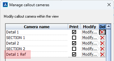
The new camera receives the same name as the model space camera but with Ref added to it to differentiate it from other cameras
View appearance options - This button is simply a shortcut to the advanced properties of the view
Visibility of cameras - Some cameras we want to print such as detail cameras and other we do not want to print such as section cameras.
However when a camera is not printed then the view does not display them making it hard to annotate that camera.
By activating this option we can show all cameras anyway independently of their print status.
The cameras that are set to no printing will not be printed even if the view is set to show all cameras with this setting.
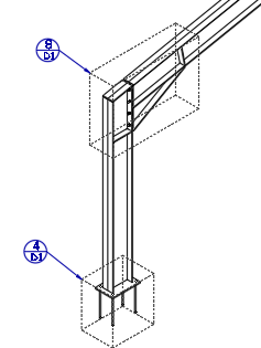
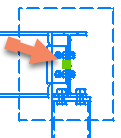
Referring cameras allow you to create many references to the same detail view for cases where the details are the same :
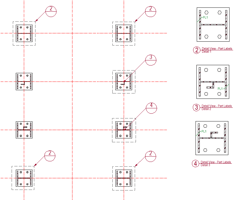
An example usage of referring cameras. There are 3 referring cameras for view number 2 on this view. It is the drafter's responsibility to see and know the difference in details such as with views number 3 and 4.
Note Parabuild does not check whether the parts within the referring camera in any way resembles the parts displayed in the referred view. It is the drafter's responsibility to make sure that the references they make matches the parts in the referred view.
 Moving a referring camera on the view
To move a referring camera the view needs to be selected first.
The referring cameras will have a grip point in the center of the camera.
Simply click on this grip to move the camera to any other location on the view.
Non-referring cameras can't be moved because Parabuild keeps their position locked to the position of the model space camera.
View symbols and callouts
View symbols and callout annotations are automatically drawn by the tools that draw plan views, section views, detail views, and adding cameras to a view, if the settings for the view and annotation style are configured that way.
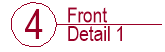
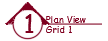
The view symbol contains the view number, the view name and the camera name.
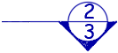
The callout annotation contains the view number above the horizontal line and the sheet number below the horizontal line.
If the referred view is on the same sheet as the annotated view then the sheet number field is empty.
View symbols and callouts will update automatically when view numbers or sheet numbers change.
|
|
|
|
View symbol example |
Section view symbol example |
|
|
|
|
Detail callout example |
Section callout example |

The annotation styles and groups themselves are explained in the Annotations topic.
The locations where the annotation groups or styles are configurable are explained hereafter :
Configuring view symbols
View symbol annotations can be configured per view.
This allows us to give a section view a different symbol than a detail view.
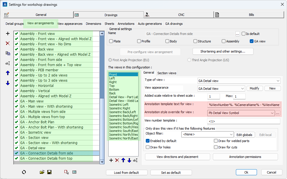
The links for getting to the location of the view symbol configurations per view are highlighted in green
If the above annotation Template text field is empty, then the template text configuration inside the annotation style will be used.
If the above Annotation style is empty then the Annotation label style of the sheet will be used for the view symbol.
The sheet's view label style can be found here :
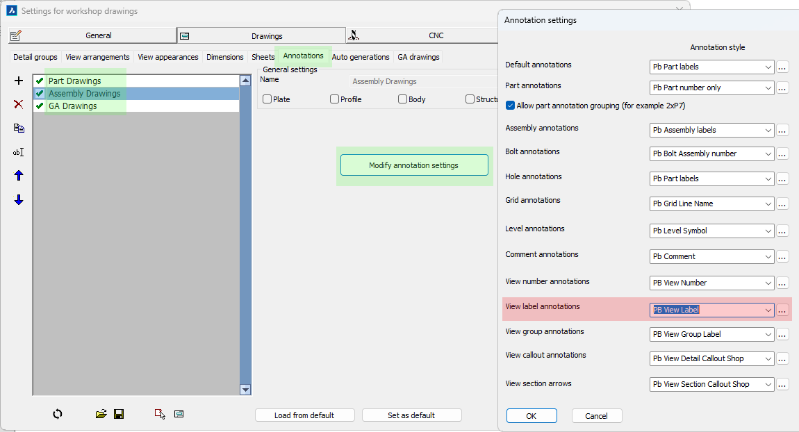
The links for getting to the location of the default view label style are highlighted in green
Manually drawing a view symbol
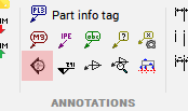
There is no direct command for drawing a view symbol but we can use this generic annotation command to draw view symbols manually :
Command name : Prb_Tag
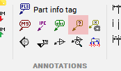
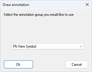
The first thing this command asks for is which annotation style of group you want to use to draw an annotation.
Choose the group Pb View Symbol :
Then simply select any point on the view that you want to annotate, after which the symbol can be drawn.
Manually drawing a callout annotation
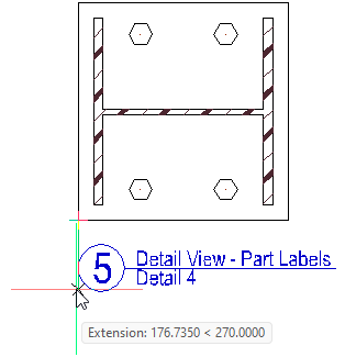
Command name : (Prb_TagGroup "Pb View Callout")
After starting this command you are prompted to select a point on the view.
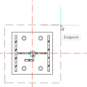
Normally this command expects you to select the center of the camera that you want to annotate.
But when the extents box of a detail is drawn on the view then we can simply move the cursor over these edges and the OSNAP endpoint will then snap to the center of that camera.
Once you correctly selected the center location of the camera you can then select the location of the callout itself :
|
|
|
|
Choosing the center point of the camera |
Choosing the location of the callout camera |

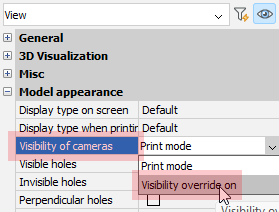 Some cameras such as section views are by default not drawn on the view. You can set the property Visibility of cameras to Visibility override on to make it possible to see and annotate all cameras in the view. This does not influence the visibility of the cameras when the view is printed.