
Stair
Command - Prb_Stair
This command will automatically draw 2 stair stringers with accompanying treads and bolts.
There are 3 basic stair models covered by this command:
- Draw a stair from the ground level (UCS World) to a beam
- Draw a stair - from beam to beam
- Draw a stair on a line
Connections between the stair stringers and the supporting steelwork may be selected from the standard range of Connections
All 3 models can be drawn with the same command.
The types of objects that you select will determine which of the 3 stair types will be drawn.
Draw a stair from the ground level (UCS World) to a beam
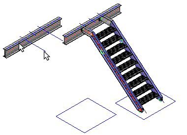 At the command line prompt:
Select the near side face of the top beam. Note! this selection will determine the direction of the stair.
As there is no bottom beam press <Enter>
Next, select either a line or profile to indicate the horizontal placement of the stair. Note! that the horizontal geometry will determine the inside face of the left hand stringer. Press <Enter>
The Stair selection dialog will appear prompting you to select the desired stair type.
The default stair will be drawn accompanied by the Stair macro edit dialog. Note! that the stair will be drawn with the top stringer aligned with the top flange of the beam
You can review the stair at any time by selecting the large macro sphere and activating the Review macro command, or you can double-click the sphere - both options will open the Edit dialog.
You can also edit components of the stair, for example the base connection, by selecting the smaller macro sphere
Draw a stair - beam to beam
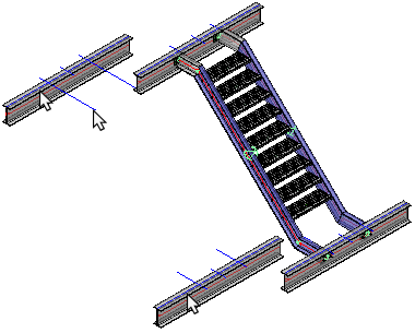 At the command line prompt:
Select the near side face of the top beam. Note! this selection will determine the direction of the stair.
Then select the bottom beam and finally the horizontal geometry, which again, may be either a line or an incoming profile. press <Enter>
The Stair selection dialog will appear prompting you to select the desired stair type.
The default stair will be drawn accompanied by the Stair macro edit dialog. Note! that the stair will be drawn with the top and bottom stringers aligned with the top flanges of the beams
You can review the stair at any time by selecting the large macro sphere and activating the Review macro command, or you can double-click the sphere - both options will open the Edit dialog.
Draw a stair on a line
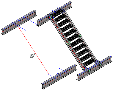 The line drawn will define the geometry of the stair, i.e. the angle and stringer length. On the image the red line was used to draw the stair.
At the command line prompt: Select the line for the stair - this will open the Stair selection dialog prompting you to select the desired stair type.
When done, press OK and the default stair will be drawn accompanied by the Stair macro edit dialog.
The stair will be constrained to the line, and by moving the line, the stair will move and the stringers, cranks, and connections will automatically follow suit.
Stair horizontal positioning
The stair will be drawn with the middle of the stair on the chosen oblique line or on the horizontal positioning geometry that you chose during creation of the stair.
But you can still choose an offset from this or change the position of the line to stick to the left or right stringer using these settings in the Stair edit dialog :
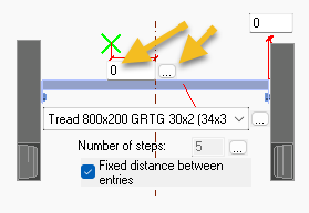
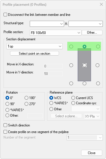
When you click on the  button to change this sticking location, you will see this dialog box appear :
|
|
This shows the profile placement dialog for a Flat bar 100x50. Big macros like the stair macro use such a flat bar as the theoretical placement location of the entire stair. The only options that are of importance to the drafter in the case of the stair are the Top-Left / Top-Middle / Top-Right radio buttons, as highlighted on the left. |
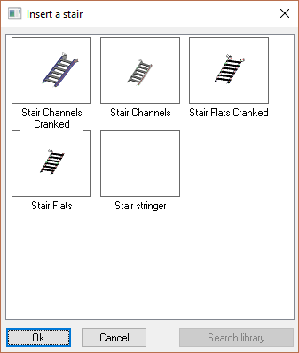 The stair selection dialog will prompt you to select the stair type - the main options include:
- Stair Channels Cranked - This selection will draw a stair with channel stringers, cranked at the top and/or bottom.
- Stair Channels - This selection will draw a stair with channel stringers but not cranked. By default, Parabuild will draw the top of the stringer intersecting the toe of the beam. This may be modified using the Stair macro edit dialog
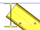
- Stair Flats Cranked - This selection will draw a stair cranked at the top and/or bottom with flat bar stringers.
- Stair Flats - This selection will draw a stair with flat bar stringers without cranks. The geometry will be the same as for Stair Channels.
The Stair macro edit dialog
The default stair is accompanied by the customization dialog:
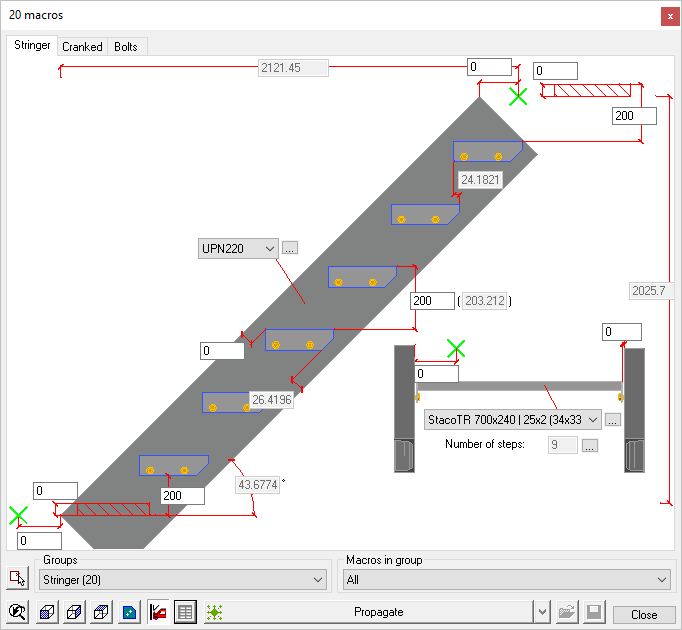
This dialog enable you to revise the geometry of the stair within the boundaries of the selected supporting steelwork. The dialog has 3 tabs:
1. / Stringer - 2. / Cranked - 3. / Bolts
The stringer tab enables you to set the profile size, stair tread risers, and the stair slope. Note! that the stair slope cab be modified directly if the stair is drawn from ground level. If the stair is constrained between a top and bottom beam, the angle can only be changed by revising the geometry of the horizontal component of the crank (Refer to the cranked tab). Or moving one of the beams up or down would also change the stair's slope.
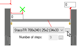
The stair treads may be set from the drop-down options - where the default options are drawn from the 'Staco' standard range. Note! that the width of the tread will determine the width of the stair.
For stair treads not included in this range, you may include standards of your choice by editing the treads table
To open the tread table, press the button  on the right-hand side of the stair tread drop-down.
Here you will see a table wherein each row represents a tread.
The columns determine the geometry of the treads, more specifically:
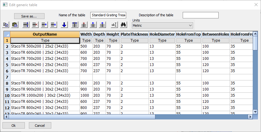
- Output name - Enter a unique name for the stair tread
- Tread width - Measured over the side plates
- Tread depth - Measured from the nosing to the back of the tread
- Plate thickness - Side-plate thickness
- Hole diameter - Bolt-hole diameter
- Hole from top - Measured from the top of the tread to the center of the hole
- Between holes - Measured as the horizontal distance between the holes
- Hole from front - Measured from the front nosing to the center of the first hole
- Chamfer front1 - Side plate front chamfer
- Chamfer front2 - Side plate front chamfer
- Chamfer back1 - Side plate back chamfer
- Chamfer back2 - Side plate back chamfer