Commande : S3d_Settings
This dialog window can be opened by clicking on the 'SET' icon.
The following is an explanation of the settings .
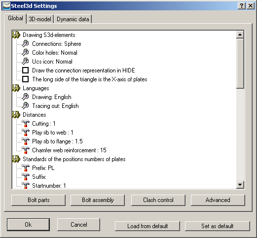
1) Global
Drawing elements:
Connections: When drawing connections you can choose to represent it by a ball, a triangle or nothing.
Hole colour: By default the colour of the holes is drawn in the colour of the beam or plate. You can set the colour to, for example, red so those holes are always drawn in red.
Languages:
Drawing: The dialogs and prompts on the command line are displayed in this language.
Plotting: If you want a different language for the text of the bill of materials and the plots (title area, …) you can select it here.
Distances:
Cutting: When cutting a beam to a plate, the distance between these two remains open. A distance of 0 is not allowed, but you can enter 0.1 or 0.01 instead of 0.
Tolerance rib to web: When Parabuild places a Rib during one of its automated routines, this tolerance is applied to the distance between the Rib and the web of the beam. We recommend a minimum of 0,01mm.
Tolerance rib to flange: This is the tolerance between Rib and flange of the beam for similar Ribs. Same minimum of 0,01mm applies.
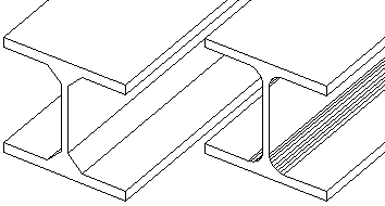
Chamfering web rib: The flange reinforcements at the end of a beam towards the head plate have a triangular body plate in the extension of the web of the beam. This plate can be chamfered at the corners using the measurement indicated here.
Standards of position numbers, mark numbers....
All position numbers can be given a prefix or a suffix. The prefixes or suffixes that are to be given to new elements can be entered here. See Numbering of elements for further explanation.
Verifying new holes after moving them: When a bolt is moved, the corresponding holes are moved with it. You can switch this off.
Weight for bill of materials: Here you fill in the weight to be used for 1 m3 of volume (mostly 8000 or 7860 kg)
Tolerance for holes: You set the tolerance for the placement of the holes that Parabuild has to allow when determining the position numbers of beams and plates.
Tolerance for plates: The tolerance in measurements of plates that Parabuild has to allow when assigning positions.
Tolerance for beams: The tolerance in lengths and cuts of beams that Parabuild can use to identify positions.
Phase:
If you want to split your project in several phases (to adapt to splits in productions or to distribute among different designers in a network) then you can set the phase using a number (1, 2, 3...).
Save extra data so that this drawing is visible in plain AutoCAD
This option allows the 'Proxy' details of a 3D-drawing to be saved. Parabuild creates its own objects (profiles, plates, bolts ...) which means that the without Parabuild, AutoCAD will not recognise these objects and therefore will not display the profiles. This is solved by the 'proxy' details, details on the appearance of the objects, which is saved within the drawing. One disadvantage of this is that the drawing becomes 5 to 7 times larger. However, this does not result in any great delay when opening or editing the drawing, as these details are not actively used, and is therefore not loaded into the memory when working with Parabuild. Remember that when this option is turned on within an existing drawing and then saved normally, the details are not yet saved. This can be solved by either setting the variable 'ISAVEPERCENT' to 0, or by saving the drawing under another name.
One final requirement is that the proxy details on the computer without Parabuild is set to display. This can be set up in AutoCAD as follows: Tools > Options > Open And Save > Proxy Images for custom objects should be set to Show proxy graphics.
Standard values for material, Comment, ...
The standard values for newly created elements can be entered here.
Bolt parts
Use this button to view/change the bolt parts.
Bolt assembly
Use this button to view/change the bolt assemblies.
Clash control
This button allows you to configure the clash control in a self explanatory dialog window.
Advanced
This button allows you to set the possible choices of materials and such like. For example when a new profile is being drawn, a material for the profile can be selected from a list. This dialog window allows the changing of this and other lists.
Set As Default: After setting your preferences you click on Set As Default. These settings will now be used for every new drawing.
Load from Default: When clicked, the settings previously saved with the button Set As Default will be loaded.
2) 3D-model
This tab determines the graphical representation (detail, ...) of profiles, plates, structures and bolts. Caution: These settings will only be applied to newly created elements, and not to existing. To edit these settings to existing elements the properties must be edited per element in the AutoCAD Properties.
3) Dynamic data
This allows you to add your own properties to plates, profiles, structures or bolts. The complete explanation can be found in the Dynamic properties chapter.