The properties of all objects drawn using AutoCAD can be changed using the Properties dialog window (lines, polylines, dimensions, solids,...).
The properties dialog window can be started in four ways:
1) The command properties on the command line
2) At the top in the toolbar Tools -> Properties
3) Select an object, using the right-hand mouse button, click on the object, and then select properties in the drop-down menu
4) Using the left-hand mouse button double click on an object.
The properties dialog window is no ordinary dialog window. This dialog window can be retained on the screen. When the dialog window is on the screen, all other commands can be carried out without interfering with the properties dialog window. This dialog window can also be integrated into the icon menus by moving it over the menus.
Just as with AutoCAD objects, Parabuild objects can also be edited in the same dialog window. When the dialog window is displayed, one or more objects can be selected and the common properties of the selected objects will be displayed immediately. These properties can then be changed as required.
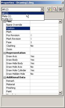
Imagine that a plate and a profile are selected at the same time. Some of the plate properties are not found in the profile, and vice versa (a plate has a thickness, a profile does not). Only the properties that the plate and the profile have in common will then be displayed. The property ‘thickness’ is not displayed, but the position number, for example is. This is however simple to bypass: At the top left of the dialog window a number of objects of the same type can be changed. In this case one plate or one profile (see illustration). Using this method, all objects of the same type can be taken from the selection in order to edit the special properties.
The properties dialog window contains another button that offers a great number of possibilities: Quick Select, the button with the funnel.
Quick Select allows the conditional selection of objects. For example, all HEA200 profiles can be selected from a drawing with a few mouse clicks, or all plates/bolts/profiles from revision 0.
Once all elements have been selected, the properties of the selected objects can be changed using the properties function.
This dialog window can also be used to view and change dynamic properties. Dynamic properties are properties applied by the user. For further explanation see the chapter Dynamic properties.
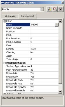
All properties explained one by one
1) Profiles
Name: The name of the profile (E.g.: HEA200). Edited by clicking on the button.
Name override: The replacement of the normal profile name. This replacement name will be used in all part lists and workshop drawings. An application example is an handrail connector: instead of using the name ‘BR33.7x2.65' this can be replaced with: 'Handrail connector 33/90°'
Position: The number automatically given to elements by Parabuild. Elements that are the same, (same dimensions, holes, sections) are given the same position number. These positions are partially adaptable with prefixes and similar, see below.
Mark: The number that Parabuild gives to every mark. When two marks in one drawing are the same, Parabuild gives them the same mark number (To be the same, the marks must contain the same position numbers and should be welded at the same locations). Partially adaptable with prefixes and similar, see below.
Pos Revision: Not directly adaptable. Can only be edited via the Revisions) system. The element will be given the current revision, not only on being created, but also when changed. Example: when a hole is added to a profile, the profile is automatically updated to the current revision.
Mark Revision: The same as pos revision. Example: when a welded profile is moved, all parts of the same mark will be given the current revision.
Phase: Adaptable. When a profile/plate is created an element will be given the current phase. The phase then remains unchanged (unless changed here manually). The current phase is located in the Global settings) dialog window.
Length: The length of the profile. Not adaptable here.
Clashing: Adaptable. This is set to yes or no and refers to whether the profile is currently clashing with other elements or not. This property is automatically set by the clash control, and is only included in properties for search objectives. For more information read the chapter Clash control.
Zoom: This is not really a property but an action: by repeatedly clicking on the button, every element in the selection is zoomed in on one by one.
Twist Angle: Adaptable: determines the angle that the profile has to turn over the length of the profile. This should only be used for profiles on a spiral path or other special 3D-forms.
Section Approximation: Determines how accurately the cross section of a profile should be drawn. This has a particular influence over curves in a cross section, for example when the rounding between a beam web and flange is applied.
Path Approximation: Determines how accurately the profile is drawn over its path. This has a particular influence over curved profiles.
Draw Axis: Draws the axis of the profile.
Draw Body: Draws the complete 3D-model of the profile.
Draw Hide Body: Draws the complete 3D-model of the profile during the HIDE command.
Draw Hole Axis: Draws the axis of every hole in the profile.
Draw Hole: Draws the cylindrical path of all holes in the profile.
Draw Hidden Hole: Draws the cylindrical path of all holes in the profile during the HIDE command.
Remark: Adaptable. Can be used in a variety of ways. This field is maintained for every element. It has its own column in the part lists, and can be used for sorting part lists and workshop drawings. This property has no further influence.
Material: Adaptable. This field also has its own column in the part lists and can be used for sorting, but this has a direct influence on the position number (and consequently the mark number). Two elements that are identical, but have another material assigned to, will be given another position number. This enables a total categorisation of different materials in part lists and workshop drawings. Example: two profiles are exactly the same except for their material property. If they were given the same position number, only one workshop drawing would be made for both profiles, and it would never be known how many, and in what material these 2 would have to be manufactured. Therefore, different materials should always have a different position number.
The weight factor of every material can be changed in the Global settings) (See advanced). Parabuild will use this weight factor to calculate the weight in the part lists.
Finishing: Adaptable. Reacts the same as 'Comment'.
Paint: Adaptable. Reacts the same as 'Comment'.
Manufacturer: Adaptable. Reacts the same as 'Comment'.
Struct group: The same as Comment. Structure groups can also be displayed in the balloon captions of 3D captions and 2D views.
Pos Prefix: Determines the prefix of the position number. For further explanation, see Numbering of elements.
Pos Suffix: Determines the suffix of the position number.
Pos Startnumber: Determines the start number of the position number.
Mark Prefix: Determines the prefix of the mark number.
Mark Suffix: Determines the suffix of the mark number.
Mark Startnumber: Determines the start number of the mark number.
Output
• Weight method:
o Default (%) : The weight of the complete length of the profile will be calculated, without subtracting the holes and cuts. In the next property you can adjust the percentage of this value that should be used.
o Cutted: The cuts in the profiles are subtracted to calculate the weight.
o Cutted and drilled: The cuts and and the holes are subtracted to calculate the weight
o Fixed value : The value you enter in the next property will be used as the weight for this element in kg (This value will be taken over in the BOMs without any adjustments).
• Weight parameter : This property is being used in combination with the above properties “Default” and “Fixed value”.
• Skip BOM : If you set this property to “Yes”, this element will not appear in the BOMs.
• Skip 2D view/3D tags : Adjust this to skip this element for the 3D tags or the 3D tags + 2D view.
• Skip drawings : You can skip only the Pos drawings, only the mark drawings, or both the Pos and Mark drawings.
User properties: All properties applied by the user in Dynamic properties) can be edited here.
2) Plates
Plate-specific properties.
Thickness: Changes the thickness of the plate.
Trac Plate: Changes the plate to normal or to end/baseplate. Endplates/baseplates are green, the normal plates are blue. End/baseplates are given an extra plate view in the assembly drawings.
3) Bolts
Orientation: The orientation of the bolt can be changed by clicking on the button.
Normal Display: The detail in which the bolt is drawn.
Hide Display: The detail in which the bolt is drawn in the command HIDE.
Display Axis: Draws the axis of the bolt.
Added length: Minimum length of the bolt = net length (material length) + nut thickness + thickness of all washers + added length. This minimum length will be used to extract the actual bolt length from the part database. The actual bolt length shall be equal to, or longer than the minimum length of the bolt.
Hole tolerance: The diameter of the bolt’s hole = hole tolerance + diameter bolt.
Bolt length: The effective length of the bolt taken from the Bolt parts database). The length of the bolt can be changed temporarily for drilling extra holes. Method: Bolt penetrates one flange of a tube; it needs to penetrate both tube flanges. Increase the bolt length enough to pass completely through the tube. Now check for new holes. The bolt will be given the correct length and the second hole will be made.
Assembly: Use this to select one of the Bolt Assemblies). A great number of properties are dependent on the bolt’s assembly.
Diameter: Select one of the available diameters from the standard bolt (the standard is extracted from the assembly).
Washer 1/2, Nut 1/2: Each part can be turned on or off separately. The standards used for these parts are recorded in the bolt assembly.
Filling washers: If the length of the bolt thread is not long enough (according to the standard) then it will not be possible to tighten the nut onto the work. This will also be visible in your drawing. Turning on filling washers will add sufficient washers enabling the bolt to be completely tightened.