Bolt
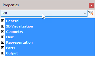
The 'Bolt' object type has the following headings:
General: Is common to all object types, and covers general AutoCAD and BricsCAD settings, including: Color / Layer / Linetype / Linetype scale / Plot style / Lineweight / Transparency / Hyperlink / Handle /
3D Visualization: Is also common to all object types and includes: Material.
The material that is referred to here is only the visual representation material. For changing the actual material of parts, see the Additional Data section of plates, profiles or structures.
Geometry
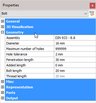
Assembly: Select a Bolt assembly from the drop-down menu. For more information refer to Bolt Assemblies
Diameter: Edits the bolt diameter
Maximum number of holes: You can enter a limit on the number of holes that this bolt can have. Parts will get holes starting from the bolt head until the maximum number of holes limit has been reached.
Hole tolerance: The diameter of the bolt's hole = diameter of the bolt + hole tolerance
Penetration length: A combination of the thickness of all the drilled part(s)
Added length: Minimum length of the bolt = net length (material length) + nut thickness + thickness of all washers + added length. This minimum length will be used to extract the actual bolt length from the part database. The actual bolt length shall be equal to, or longer than the minimum length of the bolt
Bolt length: The effective length of the bolt taken from the Bolt parts database. The length of the bolt can be changed temporarily for drilling extra holes. Method: Bolt penetrates one flange of a tube; it needs to penetrate both tube flanges. Increase the bolt length enough to pass completely through the tube. Now use the command Check for new holes on the tube and the bolt. The bolt will be given the correct length and the second hole will be drawn.
Thread length: The thread length is taken from the Bolt parts database
Misc
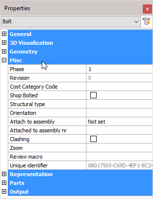
Note! - * indicates that the given value is a resultant of the sum of other values in the panel - and cannot be individually edited.
Phase: Change the project phase of the selected element
Revision: * Position revision number
Cost category code: These codes are usually determined while a quote for the project is made. This code can then later be assigned to the 3D model when the project was ordered. This way the parts can be traced from estimation to production and to completion inside ERP/MIS software. This value is exported to KISS files.
Shop Bolted: Activating the checkbox will set the bolt to shop-bolted - See Bolts/Holes > Shop Bolts
Structural type: ** For example: Bracing/Rafter/Stringer/Handrail/Post/etc....**
Orientation: Clicking on the button will switch the orientation of the bolt
Attach to assembly: From the drop-down menu, select which element the bolt should be attached to. Options include 'Closest to bolt head' or 'Closest to bolt end'
Attached to assembly nr: This will indicate which assembly number the bolt is attached to
Clashing: This is set to yes or no and refers to whether the profile is currently clashing with other elements or not. This property is automatically set by the clash control, and is only included in properties for search objectives. For more information read the chapter Clash Check
Zoom: Zoom to the extents of the selected bolt(s)
Review macro: Will open the Macro Edit dialog, where the macro may be viewed and/or edited
Unique identifier: Unique identifier allocated by Parabuild, or received from a CIS/2 or Ifc file import.
Representation
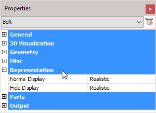
Normal Display: Selects the bolt display style in 2D wireframe
Hide Display: Selects the bolt display style in 3D Visual styles
Parts
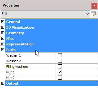
Washer 1: Enables or disables washer 1. The standards used for these parts are recorded in Bolt Assemblies
Washer 2: Enables or disables washer 2. The standards used for these parts are recorded in Bolt Assemblies
Filling washers: Enables or disables filling washers. The standards used for these parts are recorded in Bolt Assemblies
If the length of the bolt thread is not long enough (according to the standard) then it will not be possible to tighten the nut onto the work. This will also be visible in your drawing. Turning on filling washers will add sufficient washers enabling the bolt to be completely tightened
Nut 1: Enables or disables nut 1. The standards used for these parts are recorded in Bolt Assemblies
Nut 2: Enables or disables nut 2. The standards used for these parts are recorded in Bolt Assemblies
Output
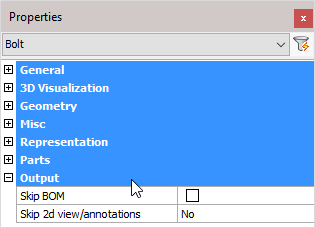
Skip BOM: If this property to ‘Yes’, this element will not appear in the BOMs
Skip 2D view/annotations: Adjust this to skip this element for the 3D annotations or the 3D annotations + 2D view
Holes
The last properties of the bolt are always the holes that the bolt may have.
All holes will be shown here separately, starting from the bolt's head the first hole will get number 1 and so on.
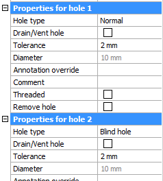
These are the properties for holes.
Hole type : Normal, Slotted, Counter sunk or Blind. For more information about the hole types, see their respective topics.
Drain/Vent hole : All the holes that are designated as 'drain / vent' holes will not receive any dimensions on the assembly shop drawings.
Tolerance : The tolerance for the hole in relation with the bolt.
Diameter : This value is only informative because it is derived from the bolt diameter and the tolerance.
Annotation override : When you enter a text in this field, this text will always be shown in the annotation of this hole on the position shop drawing. It will override the default text which would be the diameter, slotted, countersunk and thread information if they it is such a hole type.
Comment : Feel free to use this field to add comment to the hole. It will only have an effect if the variable %PbColHoleComment% is used in an annotation or in a parts list.
Threaded : See the threaded hole topic for more info about this.
Remove hole : This is an action. Clicking on the button will erase this hole.