Cladding
Command - PrB_Cladding
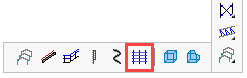
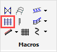
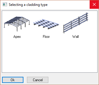
Activating this command will open the Select a cladding type dialog - select one of the options and press Ok
In this manual topic, we will explore the 3 options: Apex, Floor, and Wall
Apex
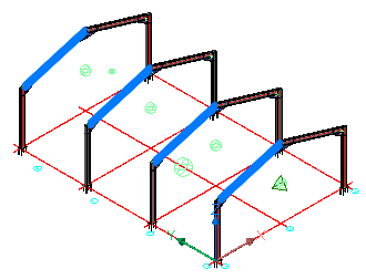
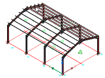
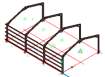
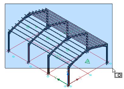
This tool will place roof purlins.
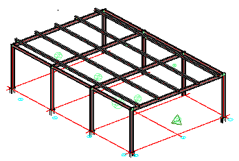
After confirming the Apex configuration, select the first row of roof beams on one side of the apex.
Then, select the next row of beams on the other side of the apex.
|
|
Select the roof beams on one side of the Apex |
Purlins after selecting Connections |
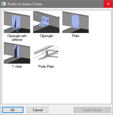
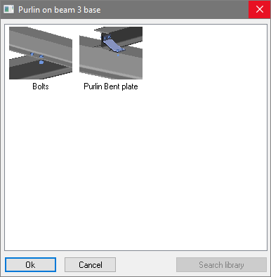
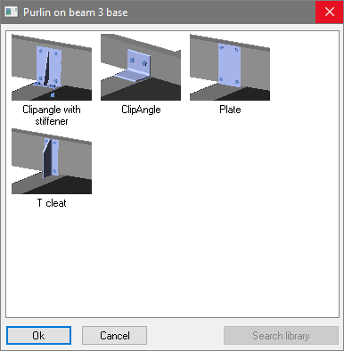
From the connection selection dialog, select the appropriate purlin to roof-beam connection.
Where the purlins are interrupted, a second dialog will appear prompting you to select the bracket at the interrupted joint.
You may skip these connections by pressing the cancel button.
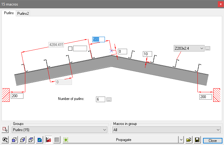
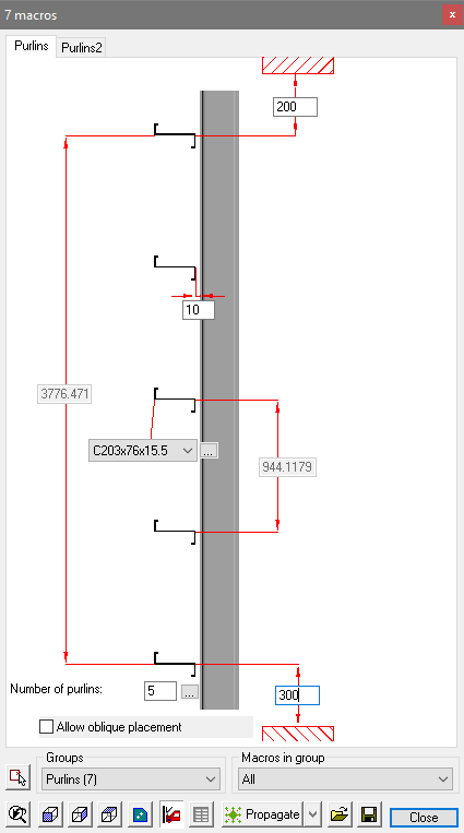
The purlins are drawn complete with the selected brackets accompanied by the edit dialog where you can change all the parameters of the purlins.
Read below to learn how to Edit the new purlin brackets
Floors
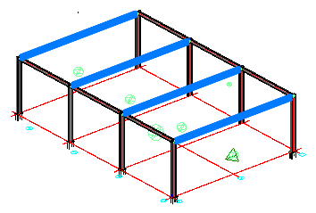
This command will place floor beams.
After choosing the Floors configuration, select the row of roof beams on which to support the floor.
|
|
Select the supporting beams |
Floor beams after selecting Connections |
From the connection selection dialog, select the appropriate floor to beam connection.
You may skip these connections by pressing the cancel button.
The floor beams are drawn complete with the selected connections accompanied by the edit dialog where you can change all the parameters of the floor beams.
Any changes will be automatically reflected on the model.
Read below to learn how to Edit the new purlin brackets
Wall
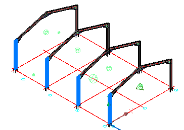
This command will place Side Cladding or Girts.
After selecting the Wall configuration, select the row of columns on which to place the side cladding girts.
At the prompt, select the side of the columns to which they are to be placed.
|
|
Select the Columns |
Side girts after selecting direction and Connections |
From the connection selection dialog, select the appropriate side girt connection.
Where the girts are interrupted, a second dialog will appear prompting you to select the bracket at the interrupted joint
You may skip these connections by pressing the cancel button.
The side girts are drawn complete with the selected connections accompanied by the edit dialog where you can change all the parameters of the girts.
Any changes will be automatically reflected on the model.
Read below to learn how to Edit the new purlin brackets
The Cladding configuration dialog
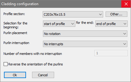
All of the options in this dialog box are explained here :
Profile Section - The profile shape and size that needs to be used for the new purlins/girts
Selection for the Beginning / End - This will set the position of the first purlin. For the roof purlins this would be the eaves of the structure, for wall girts this could be the ground floor or a concrete slab.
From the drop-down menu, there are the following options:
To Plane - Will allow you to select any column face of any profile or plate
To Grid line - Will allow you to select any grid line.
To Beam - Will allow you to select any beam.
To Column - Will allow you to select any beam. Use this for floor or apex configurations only
Start of Profile - This will measure from the start of the base profiles. This will be the selected columns in case of the wall cladding, or the selected beams in case of Floor or Apex configurations.
End of Profile - This will measure from the end of the base profiles. This will be the selected columns in case of the wall cladding, or the selected beams in case of Floor or Apex configurations.
Purlin placement - This will set the orientation of the purlin relative to the base profiles. From the drop down menus, there are the following options:
No Rotation - Accept the default rotation
Rotate follow-up row of purlins - Alternate every second purlin rotation
Rotate for Zed purlins with overlap - Zed purlins with an overlap will need a rotation for each instance
Purlin interruption - This will set the purlin span. From the drop down menus, there are the following options:
Interrupt at every location - Span the purlins between each base profile
Draw the purlins between the base members - This will draw the purlins flush : The top of the purlins will be coincident with the top of the base profiles. This also means that the purlins will be interrupted at each intersection with the base profiles.
No interrupts - This will span the purlins over the base profiles without any breaks
Skip interruption over some members - Do not break the purlins over a specified amount of base profiles.
Skip interruption over some members, Alternating - Same as above, but the breaks on the followup row of purlins will be alternated. If you use this then the interruption will not be placed on the same base profiles for all the purlins.
Number of members with no interruption - This option is to be used in combination with the above Skip interruption over some members options
Reverse the orientation of the purlins - This switches the start/end orientation of all the purlins
Edit the Purlin Brackets
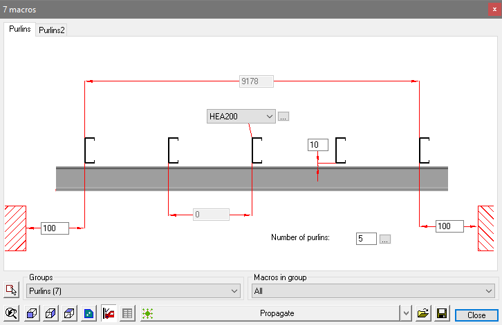
There are likely to be numerous brackets and to edit them one at a time would take too long. It is however possible to edit all the brackets simultaneously.
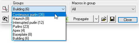
Click on the Review macro icon and block select the entire roof structure.
This will open the macro edit dialog. At the bottom of the dialog, open the Groups drop-down menu and select Continuous purlin (the number in brackets is the number of macros included in the selection).
This will automatically open the relevant edit dialog.
Note! If the option for Interrupted purlin was chosen, it will be necessary to edit the brackets separately.
This method will work for any connection type or group.