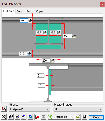
Macro Edit Dialog
The Macro edit dialog is available for all connections and will appear whenever a new connection is drawn.
Alternatively, the edit dialog may also be accessed by the Review macro command.
Each dialog is divided into 5 sections:
- The Title bar - which displays the current macro name (or the number of macros if more than 1 is being edited)
- The Tabs bar - which indicates the number of modules making up the macro. Selecting one of the tabs will open the appropriate edit dialog window. (Note! that the tabs will vary according to the selected connection type)
- The Dialog edit window - where the dimensions may be edited. This is explained in detail later in this chapter
- Bolts - (Under the Bolts tab) where you may select the bolt assembly and diameter from the drop-down menus
- The functions bar - where you may select, view, copy, and adjust macro settings. This will also be explained in detail later in this chapter.
The Dialog Edit Window
There are 4 different types of dimension controls:
- Switchable - This dimension type will be found where a dimensions is part of a string. Activating the switch will either enable or disable the dimension making it editable or responsive. A responsive dimension will automatically update when other dimensions in the string are changed.
|
|
Active |
Responsive |


- Active - an active dimension may be edited at any time

- Responsive - A responsive dimension is shown 'greyed' and cannot be directly edited, it will automatically update when other dimensions in the macro are changed, or when a dependent object in the drawing has changed. These dimensions are to be considered 'Reference dimensions'.

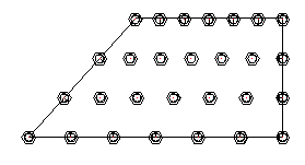
- Bolt spacing - These dimensions are found with bolt groups and can be identified by their elongated nature. There are two ways in which these dimensions are used. A single value will indicate the number of bolts to be equally spaced within the overall centers.
In the first example, there will be 3 bolts, equally spaced inside the overall centers of 140 (2 x 70)
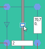
In the second example, the hole centers are specified separated by a comma (70 x 70). Any number of bolt centers may be specified.
This is particularly useful when the bolts are not equally spaced.

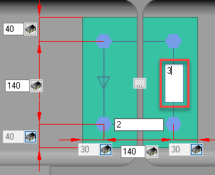

Pressing the button at the center of the section will open the Bolt pattern settings dialog, where you can perform the following actions:
Bolt Pattern Settings
This dialog comprises of 2 columns, the left hand column applies to bolts in the horizontal, while the right column applies to the vertical direction.
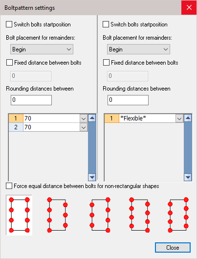
Switch bolts start position: Activating this check-box will reverse the order of the bolts, either from top to bottom, or side to side. This checkbox will only have an effect when the manual bolt spacing has been used.
Bolt placement for remainders: This option works in combination with the Fixed distance between bolts option because with it you stipulate at which side the remaining distance will be placed.
Fixed distance between bolts: The distance that you enter will always be respected.
Rounding distances between: This is an important option to avoid undesirable distances. Imagine that we have a pattern with a length of 100 mm. You choose 3 bolts for this pattern. The bolts are divided equal and as a result we get a distance between the bolts of 33.33 mm. Later that distance (rounded to 33 or 33.5) will be put on the workshop drawings, which is of course undesirable!
We avoid this by setting the rounding to 1 (or 5 or 10?). The distance between bolts is taken never smaller than the number that you enter here. Therefore with this option the bolts will never be drawn at distances of 33.33 but at distances of 33, or 35 or 30, depending on the rounding you choose.
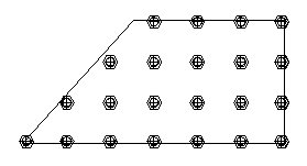
Force equal distances between bolts for non-rectangular shapes:
If you enable this option, the bolts that fall outside of the pattern will be removed.
|
|
Example with force equal distances disabled |
Example with force equal distances enabled |
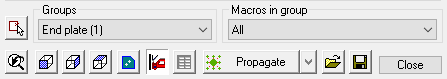
The Functions Bar
Select other macros  Activating this command will prompt you Select entities, enabling you to modify a different selection set of macros.
Groups - The drop-down menu will list all the selected macros, the number in the (parenthesis) will indicate the number of selected macros in the group. Selecting a macro will open the macro edit dialog.
Any changes that you do in the dialog will be applied to all the macros within the group. If you wish to edit only one of the macros, use the Select other macro function below.
Macros in group - From the down menu you can choose to edit all macros in the group, or only one of the macros. This second list is therefore dependent on the group that you have selected: the list will be updated each time you select another group.
View buttons
 Restore original 3D view of the selected macro
 Front view of the selected macro
 Side view of the selected macro
 Top view of the selected macro
 Front view of the current part. This button will give you a view of the parts of the current module tab : If the Bolts module is active, you will see a top view of the bolts.
 When you modify a dimension of the connection, the complete connection will be checked for collisions. This icon works as a switch to enable or disable this automatic clash control. It can be useful to turn it off when you are editing many connections simultaneously and the clash control demands too much calculation time.
 This will execute the standards on the connection again. For more information about this see the chapter Standards for connections.
Next to the propagate button, there is a drop-down button that gives us access to a range of tools that will do something with the currently active macro(s) :
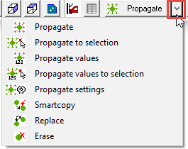
These are the purposes of all the tools :
 This tool will automatically copy the macro to all similar geometric locations in the drawing, potentially saving you a lot of time. For more information about this automation tool, see chapter Propagate.
 For more information about this automation tool, see chapter Propagate.
 For more information about this automation tool, see chapter Propagate.
 For more information about this automation tool, see chapter Propagate.
 For more information about this automation tool, see chapter Propagate.
 This tool allows you to copy the macro to other profiles. For more information about this tool, see chapter SmartCopy.
 This tool will replace the current macro with a new one from the library.
 This tool will erase the macro and all of it's components.

 With these tools you can save all values of the current selected connection(s) under a name and recall them at a later time.
Bolts
The bolt options are only available from the Bolts tab
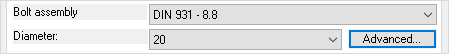
Bolt assembly - Select from the drop-down menu - The bolt assemblies can be configured, see chapter Bolt Assemblies
Diameter - Select one of the available bolt diameters from the drop-down menu
Advanced - Will open the Advanced bolt settings dialog - the settings entered here will only apply to the selected macro(s)
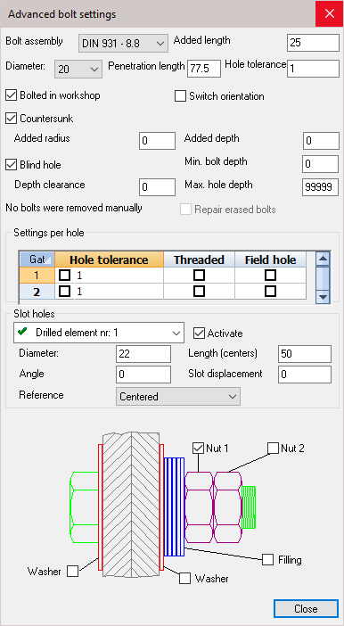
Bolt assembly - Select a new bolt assembly from the drop-down menu
Added length - increase the distance between the nut and the plate, the bolt length will increase accordingly
Diameter - Select a new bolt diameter
Penetration length - This length is calculated automatically : it is the total thickness of all the parts that are bolted together
Hole tolerance - Changes the bolt hole diameter. The value = Bolt diameter + Hole Tolerance
Bolted in workshop - Enabling this will make the bolt a shop-bolt, which will then be shown in the Position and Assembly sheet
Switch orientation - Enabling this will switch the orientation of the bolt - reversing the orientation of the nut and bolt-head
Countersunk - will change an ordinary bolt-hole to countersunk. This will enable the options to enter the countersink diameter and depth
Blind hole - This will change an ordinary bolt-hole to a blind hole. This will enable the options to enter the blind-hole depth.
Repair erased bolts - If a bolt was manually deleted, the prompt will read One or more bolts were removed manually. Checking this option will reintroduce the bolts.
Settings per hole - Here you can change the individual settings for the bolt-hole by selecting a new hole tolerance, making the hole threaded, and indicate whether its to be shop or site drilled.
Slot hole - Will change an ordinary hole into a slotted hole in one of the joined elements. Activating the checkbox will enable you to enter a hole diameter, slot length, the angle, and the slot displacement.
Finally - you can add or remove nuts, washers, and filling by checking or un-checking any of the checkboxes.