Model Lines
Using Model Lines
There are 2 ways to construct a 3D steel structure in Parabuild: A wireFrame from Model lines, and using Parabuild's unique Context Modeler. They may be used exclusively, or in tandem with one another.
Here we will look at creating a simple WireFrame model to represent a simple post and beam structure in order to demonstrate the basic principles of Parabuild.
Before constructing the WireFrame model, we should first establish a Grid and Levels. These are important to take advantage of the View functions, and more importantly, in the generation of the 2D arrangement and detail drawings.
Grid
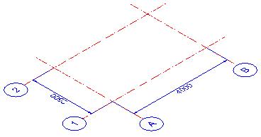
Being a very simple structure we'll establish a 2 x 2 grid, which is 4000 in the X direction, and 2500 in the Y direction - It will be drawn on the datum level WCS 0 (See The Coordinate System)
Click on the Grid icon to open the grid dialog.
Levels
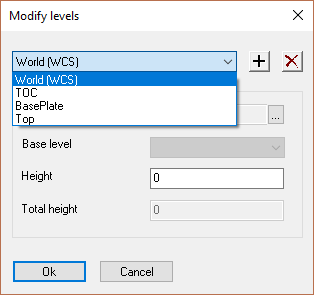
This will be a single level structure at 2750 high sitting on a foundation 200 mm above the datum, allowing for a leveling grout of 25 mm.
Therefore, we will establish 3 levels above datum = 0 (WCS), the first will be to the top of foundation = (TOC = 200). The second will be to the underside of the base plate (TOC + 25) = 225. The third will be to the top of the structure = 2750
It is possible to draw the grid using model lines, and afterwards use the Convert line to Grid line command, but Parabuild's Grid function is far simpler, quicker, and more efficient.
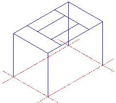
Draw the WireFrame
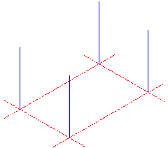
Place a vertical line to represent the columns beginning at A1 - 2750 high, (to coincide with the already established level) - repeat this process for the other 3 columns at A2, B1, and B2.
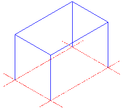
Draw horizontal lines between the 4 columns at the +2750 level to represent the outer beams
Draw 2 horizontal lines along the Y axis at 1000, 2000, 1000 - and 2 lines along the X axis between the 2 inner lines at 750, 1000, 750 - to represent the inner beams
|
|
|
|
Draw vertical lines (Columns) |
Draw horizontal lines (Outer beams) |
Draw horizontal lines (Inner beams) |
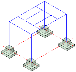
Show Foundations (Reference) |
The next step is to draw the skeletal structure based on the WireFrame:
For the purposes of this exercise, we will be using UC profiles for the Columns, and UB profiles for the beams.
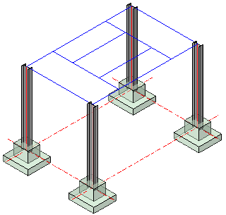
Draw the Columns
Open Draw Profiles, select I Profiles from the group / activate the UB from the group list / and select 254x146x31 from the value tables.
Scroll to the bottom of the Draw Profiles dialog and select On Model line
You will the be prompted to: Select the lines for placing the profiles : indicate the 4 column lines and press <Enter> The columns will be automatically drawn accompanied by the Profile placement dialog. Maintain the profile placement at Middle to ensure the center of the column is aligned with the model line. If necessary, Rotate the columns through 90° so that the flanges face along the Y axis. Notice that the columns are extended through the foundation to intersect with the grid line at the WCS - don't worry about this at this stage - it will be corrected when we place the base plates.
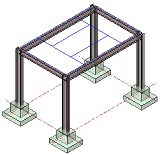
Draw the Outer Beams (Beams to Column)
Open Draw Profiles again and select I Profiles from the group / activate the UB from the group list / and select 203x133x25 from the value tables, and select and the On model line option - select the 2 outer model lines on the Y axis (Short side). Press <Enter> and the beams will be automatically drawn accompanied by the Profile placement dialog. Maintain the profile placement at Above to ensure the horizontal center of the beam is in line with the column, and the top flange is at the top of the column (2750 level). Press Close.
Repeat the process for the beams on the X axis, selecting UB from the group list and 254x102x25 from the value tables
Draw the Inner Beams (Beams to Beam)
Open Draw Profiles again and select C Profiles from the group / activate the UPN from the group list / and select UPN 200 from the value tables. Select the 2 model lines on the Y axis, press <Enter>. From the Profile placement dialog select Up left to ensure the heel of the channel is on the model line, and the top flange is in line with the top flange of the outer beams.
Open Draw Profiles again and select C Profiles from the group / activate the UPN from the group list / and select UPN 200 from the value tables. Select the 2 model lines on the X axis, press <Enter> Repeat the process above.
Note on placing Channel sections:
When placing Channels on multiple model lines, the toes of the channels may be found to point in the same direction. It may be necessary to manually mirror the profiles to change the orientation of selected profiles. Do this using the CAD 2D or 3D mirror commands.
At any time, the profiles may be edited by double-clicking on the selected profile to open the The Properties Panel.
|
|
|
Place columns |
Place outer beams |
Place inner beams |
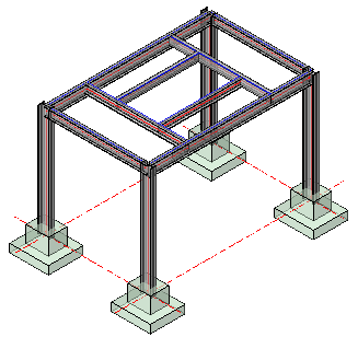
This completes the skeletal structure using model lines- next, is to look at the various connections, but first we will draw this same structure using the Context Modeler.