Using the Context Modeler
Using The Context Modeler
The Context Modeler is unique to Parabuild, and will allow you to do far more than setting out a simple post and beam structure as demonstrated in this exercise - we will be looking at these additional functions in more detail later in this user guide.
As with the WireFrame model, we should first begin with establishing a Grid and Levels. These are important to take advantage of the View functions, and more importantly, in the generation of the 2D arrangement and detail drawings.
Grid
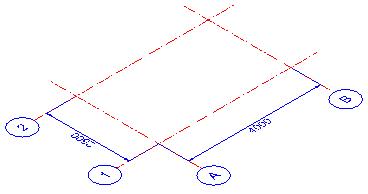
Being a very simple structure we'll establish a 2 x 2 grid, which is 4000 in the X direction, and 2500 in the Y direction - It will be drawn on the datum level WCS 0 (See The Coordinate System)
Levels
Levels may be established directly from the Context Modeler
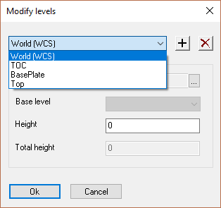
This will be a single level structure at 2750 high sitting on a foundation 200 mm above the datum, allowing for a leveling grout of 25 mm.
Therefore, we will establish 3 levels above datum = 0 (WCS), the first will be to the top of foundation = (TOC = 200). The second will be to the underside of the base plate (TOC + 25) = 225. The third will be to the top of the structure = 2750
Draw the Columns
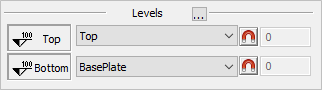
Open the Context Modeler dialog and set the Top level to Top and set the Bottom to BasePlate - These level names will coincide with those established and can be viewed and selected from the drop down options.
At any time the levels may be revised by selecting the level by name, and editing the value from the drop-down options menu. The model will reflect the changes immediately.
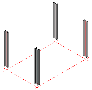
From the Context Modeler dialog, select the column profile type from the Selection options in this case we'll be using UB - 254x146x31, press the button Draw Framing. The column will hang from the mouse pointer, which should be placed on the grid line intersection (A1). Manipulate the mouse pointer so that the column is orientated correctly (The column flanges should face along the Y axis, or alternatively set the Rotation Angle while the column is still suspended. Once the column is orientated properly, press <Enter>, the selected orientation will remain while you click and <Enter> the remaining (3) column positions. Note that the selected levels will be taken into account.
Draw the Outer Beams
 From the Context Modeler dialog, select the beam profile type from the Selection options in this case we'll be using UB - 203x133x25. Select the option, Draw a beam between columns
  and select Draw Framing. Place the mouse pointer between the columns on the Y axis - the column will be shown hanging from the pointer between the columns - when satisfied with the positioning press the left mouse button to confirm the selection. The beam height may be adjusted by moving the mouse pointer or editing the dimension shown in the edit box. You may re-visit the positioning at any time by selecting the beam and editing the edit box.
Using the same method, select UB - 254x102x25 from the Selection options and place them between the columns on the X axis.
Draw the inner beams
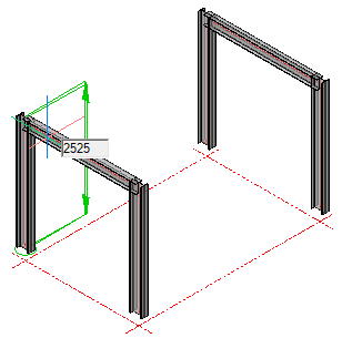
 From the Context Modeler dialog, select the beam profile type from the Selection options in this case we'll be using UPN - 200. Select the option, Draw a beam between beams
  and select Draw Framing. Place the mouse pointer between the outer beams on the X axis - the beam will be shown hanging from the pointer between the outer beams - moving the mouse pointer will display the current position from its grid reference point. Set the position at 1000 mm from the A grid line.
when satisfied with the positioning press the left mouse button to confirm the selection. You may re-visit the positioning at any time by selecting the beam and editing the edit box.
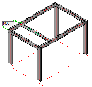
Repeat the process by placing a beam 1000 mm from the B grid.
Finally, From the Context Modeler dialog, select the beam profile type from the Selection options in this case we'll be using UPN - 180 and place them between the last 2 beams at 750 mm from the 1 and 2 grid lines using the same procedure.
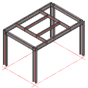
In this example, ensure that the toes of the channels face outwards by using the Rotate Profile command, and that the dimension is placed to the heel of the channel. This can be done by Editing the profiles.
Completed Skeletal Frame
Editing Profiles:
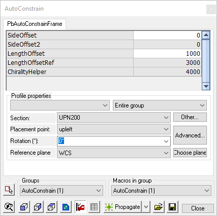 At any time, profiles placed using the Context modeler may be edited - this includes the profile type and size, its location, and its orientation. This is done by double-clicking the selected profile to open the Auto Constrain dialog.
To ensure channels are placed at the heel of the channel, set the placement point to up left
This completes the skeletal structure using the Context Modeler- next, is to look at the various connections.