Connections
Connections
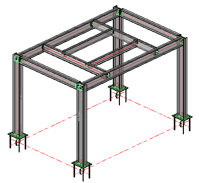
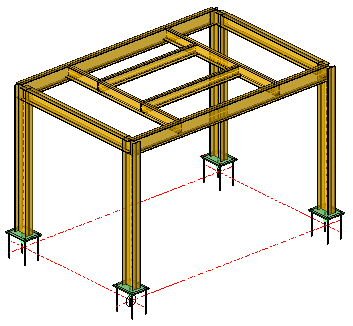
To complete this very simple structure, we'll now add some connections, beginning with the base plates
Base Plates
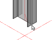
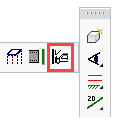
Select Connections - End / Base Plates  from the main menu and following the command line prompt Select Entities - indicate the base of the column - The base plate selection dialog will appear.
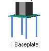
Select I BasePlate from the dialog and press <Enter> - the default Base plate will be drawn. You will notice that the base plate has been drawn at the WCS (0) and the column extended - this will be corrected in the customization dialog.
Press <Enter> again to open the Customization dialog. Here you are able to set the plate size and thickness, bolt pattern, and relationship to the column
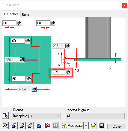
Editing the Base Plate Dialog
The dialog as 2 tabs - BasePlate - where you may edit the plate size and thickness, and Bolts - where you may edit the bolts pattern.
(For more information about the editing dialog boxes see Review Macro)
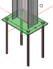
In this instance, as we noted, the base plate was re-situated at the WCS, to correct this, edit the dimension from the WCS from 0 to 225. This will bring the base plate back to its intended position.
Notice also, that the base plate is colored green - to indicate it is a base plate welded to the column - doing this will ensure the base plate will get an additional view on the workshop drawings.
Copy the Base Plates to the other columns
Once the base plate has been customized to suit, this may be copied by using the Smart Copy command, or alternatively, use the Propagate command
Warnings / Clash Detection
Parabuild has recognized that we are placing connections and has changed the color of the structure to yellow - this is to serve as a warning that there are clashes between the elements. This is normal, because at this stage the elements of the structure are intersecting due to the lack of any connections.
Bolts are also colored yellow when they are too close to a plate or beam. Bolts will be colored red if they are drawn in the air or if they are too close to the edge of a beam or plate that they are connecting.
The maximum distance between a bolt and the edge of a beam or plate can be set in the Global settings / Clash control dialog.
As the connections are resolved and clashes removed, the model will revert to its default Grey color. When the entire model is grey, indicating there are no further clashes, its safe to proceed with he preparation of workshop drawings.
You may also manually check for clashes using the Clash check command
Beam to Column Connections - (Beam to column flange)
Select Connections / Beam to Column Connections  from the main menu and following the command line prompt, Select the continuous column - followed by Select the beam. Note - Always select the column first - followed by the beam. Reversing the order will cause unpredictable results - if you make this mistake, correct it using the Back button.
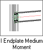
The Beam to continuous column selection dialog will appear. Parabuild has recognized that the intended connection is connecting an I-Profile beam to the Flange of the column and has automatically filtered the options to reflect this particular configuration. This filtering mechanism simplifies the selection process.
Select I EndPlate Medium Moment from the dialog and press <Ok> - the default End plate will be drawn.
Press <Enter> to open the Customization dialog. Here you are able to set the plate size and thickness, bolt pattern, and relationship with the beam.
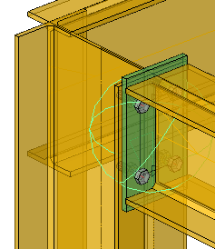
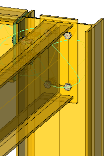
It's clear from this example, that the end plate will require some editing. The bolt diameter is too small, and the end plate protrudes above and below the beam - for a medium moment connection connecting anywhere but the top of the column, this would be OK, but in this particular instance it's not a good idea.
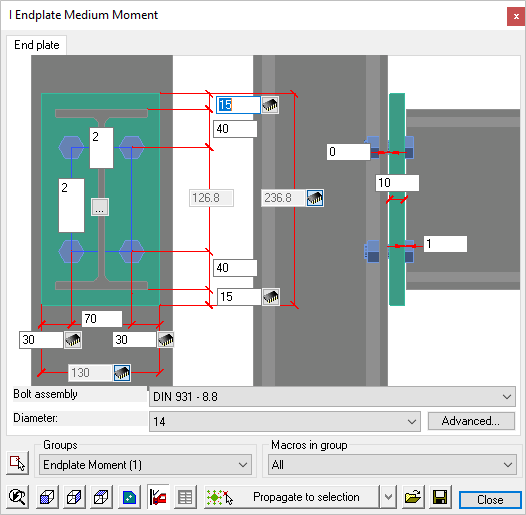
Editing the dialog
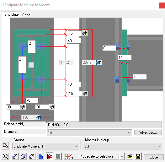
The first thing to change is that end plate protrusion, so we'll change the dimension (Top and Bottom) from 15 to -6 - this will allow for a 6 mm fillet weld. Next we'll change the weld gap from 1 to 0, and increase the clearance between end plate and column from 0 to 2 mm.
Next, we'll change the vertical bolt pitch to 70 / 70 measured from the top of the beam flange - leaving the horizontal gauge at 70 mm with an edge distance of 30 mm.
Finally, we'll increase the bolt diameter from 14 to 16
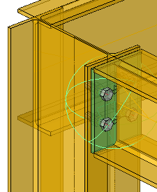
Press Close when complete
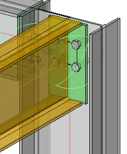
See the edited dialog and connection below.
(For more information about these editing dialog boxes see Review Macro)

Copy the End Plate to the other connections
Once the end plate has been customized to suit, it may be copied by using the Smart Copy command, or alternatively, use the Propagate command.
Beam to Column Connections - (Beam to column Web)
Select Connections / Beam to Column Connections from the main menu and following the command line prompt, Select the continuous column - followed by Select the beam. Note! - Always select the column first - followed by the beam. Reversing the order will cause unpredictable results - if you make this mistake, correct it using the Back button.
The Beam to continuous column selection dialog will appear. Parabuild has again recognized that the intended connection is connecting an I-Profile beam to the Web of the column and has automatically filtered the options to reflect this particular configuration..
Select I EndPlate Medium Moment again from the dialog and press <Ok> - the default End plate will be drawn.
Press <Enter> to open the Customization dialog. Here you are able to set the plate size and thickness, bolt pattern, and relationship with the beam.
As before, the end plate will require some editing. The comments that apply to the beam to column flange connection, apply here.
Editing the dialog
we'll again change the dimension (Top and Bottom) from 15 to -6. Next we'll change the weld gap from 1 to 0, and increase the clearance between end plate and column from 0 to 2 mm.
As before, we'll change the vertical bolt pitch to 70 / 70 measured from the top of the beam flange - we'll leave the horizontal gauge from 70 to 90 mm with an edge distance of 30 mm.
Finally, we'll again increase the bolt diameter from 14 to 16
Press Close when complete
See the edited dialog and connection below.
(For more information about the editing dialog boxes see Review Macro)
Note! When detailing end-plates, it's always a good idea to round-off the overall dimensions when possible. In this example, the plate depth has worked out to 242.2 mm and though this is strictly correct, it would be better to round it off to a round figure and compensate the difference by revising the lower end-plate dimension to -6.2. which is effectively a reference dimension.

Beam to Beam Connections
Select Connections / Beam vs beam  from the main menu and following the command line prompt Select the continuous beam (Supporting beam) - followed by Select the 2nd beam (Connecting beam) - The Beam vs beam selection dialog will appear.
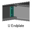
Select U EndPlate from the dialog and press <Enter> - the default End plate will be drawn.
Press <Enter> again to open the Customization dialog. Here you are able to set the plate size and thickness, bolt pattern, and relationship to the column.
Note that Parabuild has recognized that the connection is a Channel section to an I beam - and automatically selected the appropriate dialog.
The default connection is 2 bolts situated vertically. We will change this to a 4 bolt connection with the bolts placed horizontally equally about the heel of the channel, with a vertical pitch of 70 / 70.
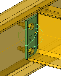
Being a beam-to-beam connection Parabuild has recognized that a top flange cope is necessary.
Editing the dialog
This dialog has 3 tabs - End Plate / Bolts / Copes
The Copes tab
First, we'll check the Copes - the default depth is 30 mm - we can check this by looking at the reference of 21.6 mm which should be greater than the root radius of the beam. In this case, it is.
Next is the clearance of 10 mm between the toe of the supporting beam and the flange of the connecting beam - in all but the largest beams, this will be OK.
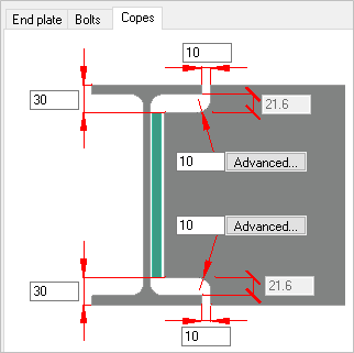
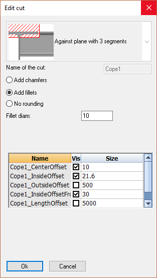
The default fillet radius for the notch is set at 10 mm - which is good practice - selecting the advanced button will open the Edit Cut dialog where you have the option of changing the fillet radius, making it a chamfer, or leaving it out altogether.
Additionally, you may edit all the other cope properties.
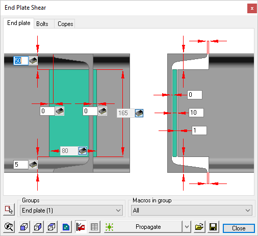
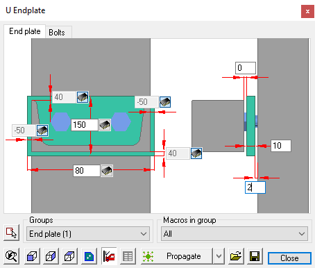
The end plate tab
Next we'll open at the end plate tab. General practice is to set the top of the end plate equal to the depth of the cope, which in this case is 30 mm.
As we are making a 4 bolt connection, we'll increase the end plate width from 80 to 150, and to center the plate about the heel of the channel, we'll set a dimension of 75.
Next we'll change the weld gap from 1 to 0, and increase the clearance between end plate and column from 0 to 2 mm.
The depth of the end plate we'll set at 150 - the reason for doing this will be explained when we look at the bolts.
|
|
Before Editing |
After Editing |

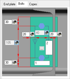
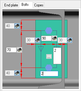
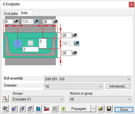
The bolts tab
As mentioned earlier - this will be a 4-bolt connection with the vertical pitch of 70 / 70 mm. measured from the top of the incoming beam, and a horizontal gauge of 90 mm.
Here we will change the horizontal number of bolts from 1 to 2, Edit the horizontal gauge from 40 to 90, leaving a horizontal edge distance of 30 mm.
In order to maintain the 70 / 70 vertical bolt pitch, edit the dimension from the top of the end plate to the first row of bolts from 30 to 40 mm. This, added to 30 mm from the top of the beam (Depth of cope) = 70 mm.
Edit the vertical bolt pitch from 105 to 70 mm.
(For more information about the editing dialog boxes see Review Macro)
|
|
|
Before Editing |
After Editing |
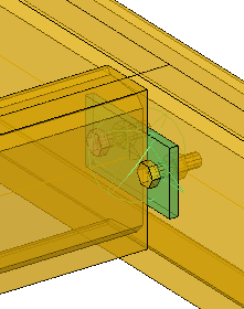
The Completed Connection |
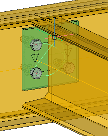
Next, we'll connect the inner beams to each other using another variation of the end plate. As with the previous connection, select the supporting beam, followed by the connecting or incoming beam. From the connection selection dialog select U EndPlate - The default connection will be drawn - Press <Enter> to open the U EndPlate edit dialog.
Note that Parabuild has again recognized the orientation of the connection and presented options compatible with the configuration. Once selected, the edit dialog likewise, reflects the particular configuration.

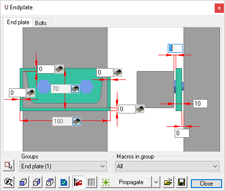
Editing the dialog
This dialog has tabs - End Plate / Bolts
The editing procedure is exactly the same as the previous connection. In this case, we'll provide a 2-bolt connection at a horizontal pitch of 90 mm
The end plate tab
As we are making a 2 bolt connection aligned horizontally, we'll increase the end plate width from 70 to 150, and to center the plate about the heel of the channel, we'll set a dimension of 75. The depth of the end plate will be set at 80 mm.
Next we'll change the weld gap from 1 to 0, and increase the clearance between end plate and column from 0 to 2 mm.
The depth of the end plate we'll set at 80 - again, this will be to accommodate the bolts at the bolts.
|
|
Before Editing |
After Editing |
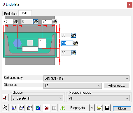
The bolts tab
As this will be a 2-bolt connection, the vertical pitch will be set at 70 mm to the row of bolts measured from the top of the incoming beam, and a horizontal gauge of 90 mm.
Here we will change the vertical number of bolts from 2 to 1, Edit the horizontal gauge from 14 to 90, leaving a horizontal edge distance of 30 mm.
Edit the dimension from the top of the end plate to the row of bolts from 28 to 40 mm. This, added to 30 mm from the top of the beam (Depth of cope) = 70 mm.
Edit the vertical bolt pitch from 124 to 0 mm.
(For more information about the editing dialog boxes see Review Macro)
|
|
Before Editing |
After Editing |
Once the base plate has been customized to suit, it may be copied by using the Smart Copy command, or alternatively, use the Propagate command
Below is the completed connection
The Completed structure