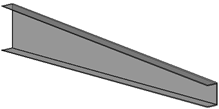
Draw Profiles
These are all the different section shapes that can be used to draw profiles :
|
I - Profiles |
C - Profiles (Channels) |
|
L - Profiles (Angles) |
|
T - Profiles (Tees) |
|
Built-Up Profiles (Plate Girders) |
|
Hollow Sections ( Circular, Square, Rectangular) |
|
Flats / Bars / Rounds |
|
Cold Formed Profiles(Purlins and Side-Rails) |
|
Others |
|
Custom Shapes - User Defined |
|
Plate with PolyLine , Lowering a Member, Corrugated Sheet Sections, Miscellaneous, Add to Elements Library, Add to Custom Shapes Library |

Selecting any of the above will bring up the Select profile dialog, but based on the icon that you selected a different tab will be pre-selected.
There are 3 ways to draw profiles:

- On model line with this dialog - Simply select all of the model lines on which you want to draw profiles.
With the model line option, profiles can be drawn on the following line types:Line
- Arc
- 2D PolyLine
- 3D PolyLine
- Spline
- Parabuild helix - Command : PrB_Helix

- Parabuild 3D polyline, which has a bit more flexibility with regards to arcs in 3D than the AutoCAD/BricsCAD 3D polyline. Command : PrB_3dPoly
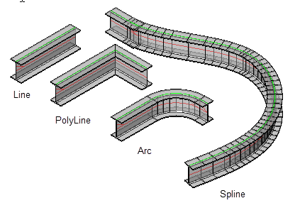
Note that PolyLines, Arcs, and Splines should be 'open-ended'. This command will not work with circles or rectangles. Also the model lines should never be self-intersecting.
- Choose 2 points with this dialog - The user is prompted for the first and second points on the baseline, after which the above dialog and options are displayed. The points may be placed anywhere on the drawing.
- Alternatively, using a different tool entirely called the Context Modeler
Select Profile
We will explore all of the options in this dialog :
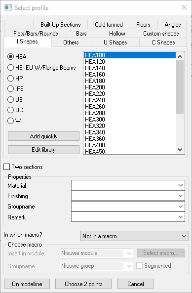
The top of this dialog lists the profile Groups, which correspond with the toolbar icons.
The left side column lists the Types contained within the specified group - the radio button, when activated, will display the available sections of the specified type.
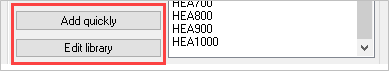
There are options to add to, or edit the library. See Editing the Profile Library
Morph 2 Sections
With the Two sections checkbox checked, you may morph 2 Profile sections.

To do this, you must begin by drawing the profile the normal way - once the selected profile has been drawn, the Profile placement dialog will appear enabling you to enter the second profile.
A prerequisite for this function is that the two sections have the same number of segments. Otherwise, a logical sequence cannot be created; The transition is being made from segment to segment (a segment is a section of straight line or curve section of a PolyLine)
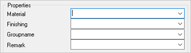
Profile Properties
Below the profile section you may enter 4 properties that the new profiles will receive. To avoid typing these values each time, they may be entered as standards by using the Parabuild settings > Global tab
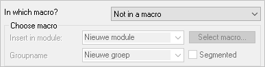
Add new profiles to a macro
These settings are relevant if you wish to add the new profiles to a macro. This is useful if you wish that the profile stays dependent on the model line with which it was drawn. If the model line changes, the profile will modify automatically. It is the macro that keeps the link between the line and the profile intact.
After the profile is drawn, the following dialog will appear, offering the following options:
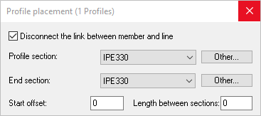
Profile placement
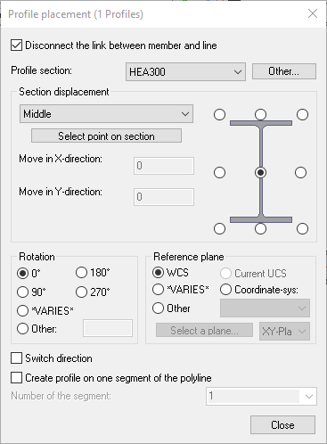
- Disconnect the link between the member and line - With the checkbox Unchecked, the profile will be constrained to the line. That is to say, the member cannot be moved independently of the line. See Constrained Profiles
With the checkbox activated, the member may be moved independently of the line.
- With the Profile section DropDown menu, the user is able to change the profile section - while selecting Other, the user is able to select a profile from another group.
- The Section displacement enables the user to select the appropriate displacement point on the member, this may be done by activating the appropriate radio button, or selecting an option from the drop-down menu.
- It is possible to match the rotation of the member to another part by manually selecting a reference plane
- With the checkbox 'Switch direction' activated, the user is able to switch the direction of the member on its axis.
- With the checkbox 'Create profile on one segment of the PolyLine, the user is able to select the applicable segment.