Pre-configure View Arrgt.
The Pre-configure dialog box will change and re-arrange the views of the profile or assembly settings.
Using this dialog box can cause a reset of all of your views.
It is therefore best to first use this dialog to configure the views.
If needed after that you can tweak the arrangement some more with the View Settings and Configure view directions dialogs view.
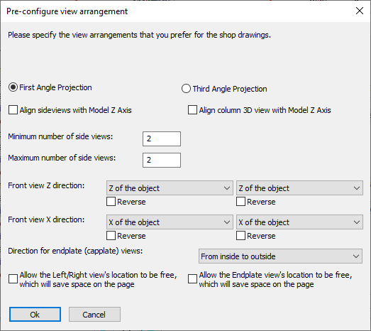
In this dialog box you can change the following options :
First angle projection - This option will arrange the side views and the left/right views so that they are arranged according to the First angle orthographic projection.
First angle orthographic projection is used often in the EU.
Third angle projection - This option will arrange the side views and the left/right views so that they are arranged according to the Third angle orthographic projection.
Third angle orthographic projection is used widely in the USA.
Align side views with model Z axis - When activated, columns will be drawn upright, beams horizontal, rafters sloped, etc...
Each part will have the same slope in 2D as it does in 3D.
When deactivated, the main member of the assembly will be drawn horizontal on the page.
Align column 3D view with Model Z axis - When activated, the 3D view of columns will be drawn upright.
The 3D view of all other assemblies will be drawn horizontal, even rafters and bracings.
Minimum/Maximum number of side views - The difference between the minimum and maximum number of side-views determines how many side-views will be activated dynamically.
A dynamically chosen side-view is a view that will only be drawn when there are parts on the view that would be invisible on the minimum side views.
If you want a fixed number of views, set minimum and maximum to the same number.
Front view Z direction - The Front view is the main view, on which most other views are based.
The Z direction is the viewing direction.
With this option you can choose the viewing direction to follow :
- The object itself, so that we're looking at the part locally (this is the default)
- The world directions, so that we can look at it from the 3D model's direction
- The cardinal directions. The AutoCAD/BricsCAD variable NORTHDIRECTION will be used to determine the cardinal directions in 3D. The front view will then point to the North/South/East/West direction in the 3D model.
This option works in combination with the Align side views with model Z axis option.
The Align side views option decides most of the placement of the side views. The Front view Z direction option only has an influence on the viewing direction of the side views
Front view X direction - This is the same as Front view Z direction, but this relates to the X direction of the view instead of the viewing direction.
The Y direction of the view is derived from the Y and X directions.
Direction of End plate views - Use one of the options to change the viewing directions of all of the end plate views
Allow Left/Right view's location to be free - When this is enabled, the Left/Right views will not be located next to the correct side views as instructed by the angle projection rules.
One would enable this to allow Parabuild to fit the part on a smaller format and a better scale because Parabuild will be able to move the view to a free space.
Allow the endplate view's location to be free - Same as above but this applies to all the endplate views.
The endplate views are not restricted by the angle projection rules.